Boundary Scan: 5 Steps That Lift Test Coverage
Boundary scan is a test method that uses the shift register built into a digital device to drive and read the pins around it. Instead of pressing a probe onto a net, the tester shifts a pattern through the chain and compares what comes back, so a net can be checked even when it is buried under a component or hidden on an inner layer.
It complements a bed of nails rather than replacing it. A fixture can reach an analogue node and a power rail that no scan cell controls, while the scan reaches the fine pitch devices and the buried vias that no probe can land on. Deciding which method covers which net is the engineering work.
What Boundary Scan Can and Cannot See
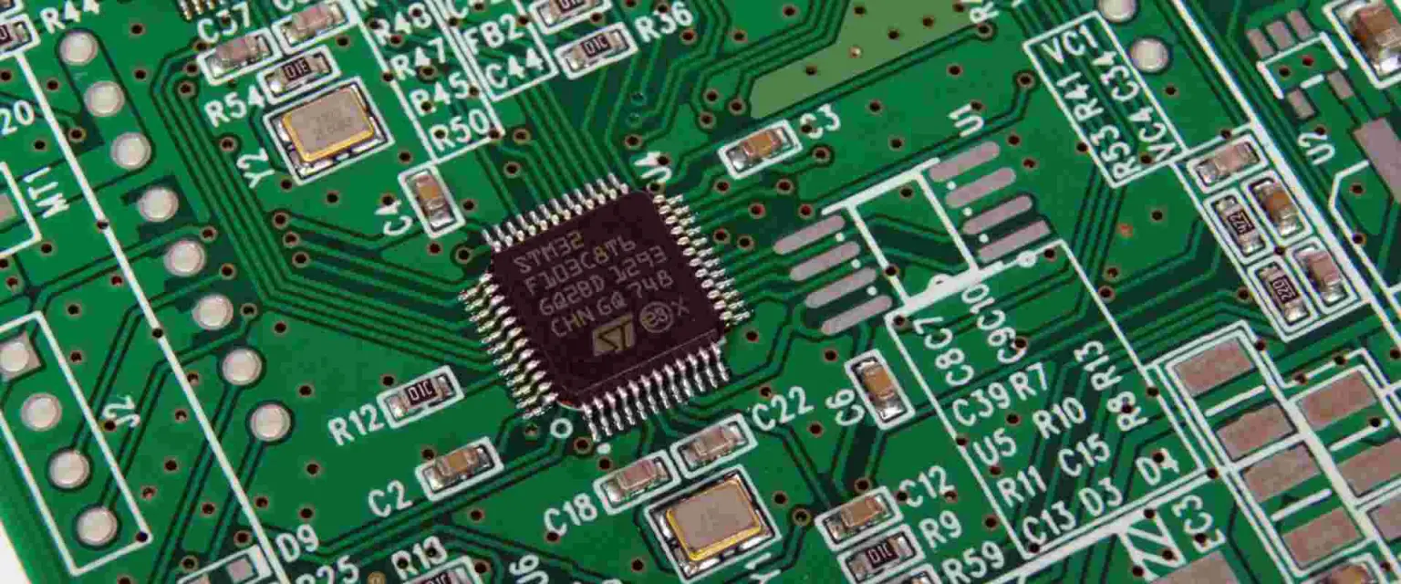
Scan cells sit inside the device and are connected to its pins, so the method sees the logic side of a connection rather than the physical solder joint. A short between two nets, an open trace and a wrong device are all detectable, while a cracked solder ball that still makes contact when the board is cold is not.
The method also depends on the device being powered and its clock running. A rail that never comes up, a reset held low or a missing supply will stop the chain from closing, and the failure is reported as a scan problem when the real cause is the power circuit feeding the device.
Building the JTAG Chain on the Board
Devices are connected in a daisy chain through their test data in and test data out pins, with a shared clock, mode select and reset. The order of the devices matters, because the tester has to know the length of every register in the chain to place a pattern on the right pin.
A chain that crosses a connector, a board to board link or a cable is harder to control than one contained on a single board. Where the chain leaves the board, the design should provide a way to bypass the missing section, or the test plan will depend on a mating half that may not be present at the test station.
Test Coverage: Counting What Is Reached
Test coverage is the share of nets that the chosen methods can actually exercise and observe. It is calculated from the netlist and the device models rather than estimated, and the number should be reported before the board is released for tooling, when a change is still cheap.
A high coverage figure deserves a second look at how it was produced. Nets that are only driven and never observed, or that are observed through a device that is itself untested, are often counted as covered when they are not, and that gap shows up later as a field return.
The Netlist and the Boundary Scan Model
The model describes what each device can do with its pins, and it must match the part actually placed on the board. A model taken from a similar device, or from an earlier revision, will produce a chain that closes but tests the wrong pins, which is far more dangerous than a chain that fails outright.
The netlist has to come from the same revision as the fabrication data. Where the schematic is updated without reissuing the netlist, the test program and the board disagree, and the symptom is a handful of nets that fail on every board in a way that looks like a layout error.
When a Fixture Still Makes Sense
A fixture earns its cost where the product has analogue blocks, power sequencing, or connectors that need to be exercised at speed. Those functions cannot be reached through digital pins, and the physical contact also proves that a pad can be probed, which matters for a board that will be tested again in service.
The decision should be made per net rather than per product. A board can run scan on most of its logic and still need a small fixture for a handful of nodes, and that combination is usually cheaper than either method alone, especially on low volume builds where tooling cost is hard to amortise.
Design Rules for Chain Access
The chain needs a header or test points that the station can reach, and those points need to be placed where a probe or a cable can sit without fouling a tall component. Where the header is inside a shielding can, the design should provide access or the test plan must rely on a different route.
Chain clock and data lines should be routed with the same care as any other signal, because a long stub or a badly terminated line produces a chain that closes on the bench and fails on the line. Our design for test notes cover the layout rules that keep the chain reliable.
Programming, Flash and the Same Chain
The same chain that tests the board can usually program it. Flash memory, serial configuration devices and small microcontrollers can be loaded through the test access port, which removes a separate programming step and the handling that goes with it.
Programming through the chain does add time to the test, because the image has to be shifted in at the clock rate of the interface. Where the image is large, the programming step is often split so that the board is tested first and programmed only after it passes.
Debugging a Chain That Will Not Close
A chain that will not close is usually a power, clock or reset problem rather than a scan problem. The first checks are the supply rails at the device, the state of the reset line and the presence of the clock, all measured at the pin rather than assumed from the schematic.
Where the chain closes but the identifiers read incorrectly, the fault is often a wrong device or a rotated package. The identifier readout is the quickest way to prove what is actually fitted, and it should be logged at the first article so that later changes are visible. Our in-circuit test notes cover the fixture side of the same station.
Records and Coverage Sign Off
The record should hold the chain description, the device models and their revisions, the coverage figure and the nets that are left uncovered. Signing off a test plan without the uncovered list means the risk has not been assessed, only hidden.
Where a net is left uncovered, the reason should be written down: no access, no model, or a function that another test already proves. That list is the first document to read when a defect escapes, and our bare board test notes describe how the same discipline is applied before assembly.
Working With the Assembly Partner
The test plan is a joint document between the design team and the shop that will run the station. The design team knows what each net does, while the shop knows what the station can reach, and the coverage figure only becomes realistic when both have signed it.
The plan should be reviewed whenever the board revision changes, because a new component, a moved header or a changed power tree will alter what the chain can do. The IEEE standard behind the method defines the register behaviour that the models describe, and the review is the point where that theory meets a real panel.
FAQ
Is boundary scan enough on its own? Rarely. It covers the digital logic well and the analogue and power sections poorly, so most products use it alongside a fixture, an optical check and a functional test. The mix follows the board rather than a preference for one method.
Why does the chain work on the bench but fail on the line? Cable length, station grounding and the state of the power supply are the usual differences. A chain that closes on a bench supply can fail on a station where the rail ramps more slowly, so the test should be proved on the production station before release.
How often should the models be updated? Whenever a device changes, and at every board revision. A model set is part of the test program and should be under the same revision control, or the station will be testing a board that no longer exists.