Pigtail and Drain Wire Practice for Shield Transfer Impedance
A screen around a cable is only as good as the way it is terminated. The shield intercepts the field that would otherwise couple onto the conductors inside it, and the current it collects has to be returned to a reference. Every centimetre between the screen and that reference is an inductance, and that inductance is what decides whether the cable behaves as a screened cable or as an antenna with a decorative braid.
What the Shield Does
Cable shield termination is the way a conductive layer around the conductors that reflects and absorbs the fields arriving from outside and contains the fields produced inside. Both functions depend on the same mechanism: the current induced in the shield has to find a low impedance path to the reference.
The shield does not block the field, it diverts the current. When the current path is short and wide, the current flows on the outside of the shield and the conductors inside see almost nothing. When the path is long and thin, the current develops a voltage that appears in series with the signal.
The measure of the quality is the transfer impedance: the ratio between the voltage induced in the circuit inside the cable and the current flowing on the shield. A good termination keeps the transfer impedance low over the frequency band of interest, and a poor one raises it by orders of magnitude.
Termination Methods Compared
The methods run from the best to the worst in a fairly short list. A 360 degree clamp that grips the whole circumference of the shield against a metal entry plate is the best, and it is also the most demanding on the mechanical design.
A connector with a metal shell and a backshell that clamps the braid gives almost the same performance, provided the shell is bonded to the chassis. The path from the braid through the shell to the panel is short and has a large area.
A pigtail, in which the braid is gathered into a wire and soldered to a pin or a stud, is the worst of the common methods. The braid is not a good conductor in the way a wire is, and a strand that is gathered and twisted has a much higher impedance than the braid itself.
The ranking applies at every frequency, but the difference between the methods grows with frequency, so a product that passes at one megahertz can fail at a hundred with the same termination.
The Pigtail Problem
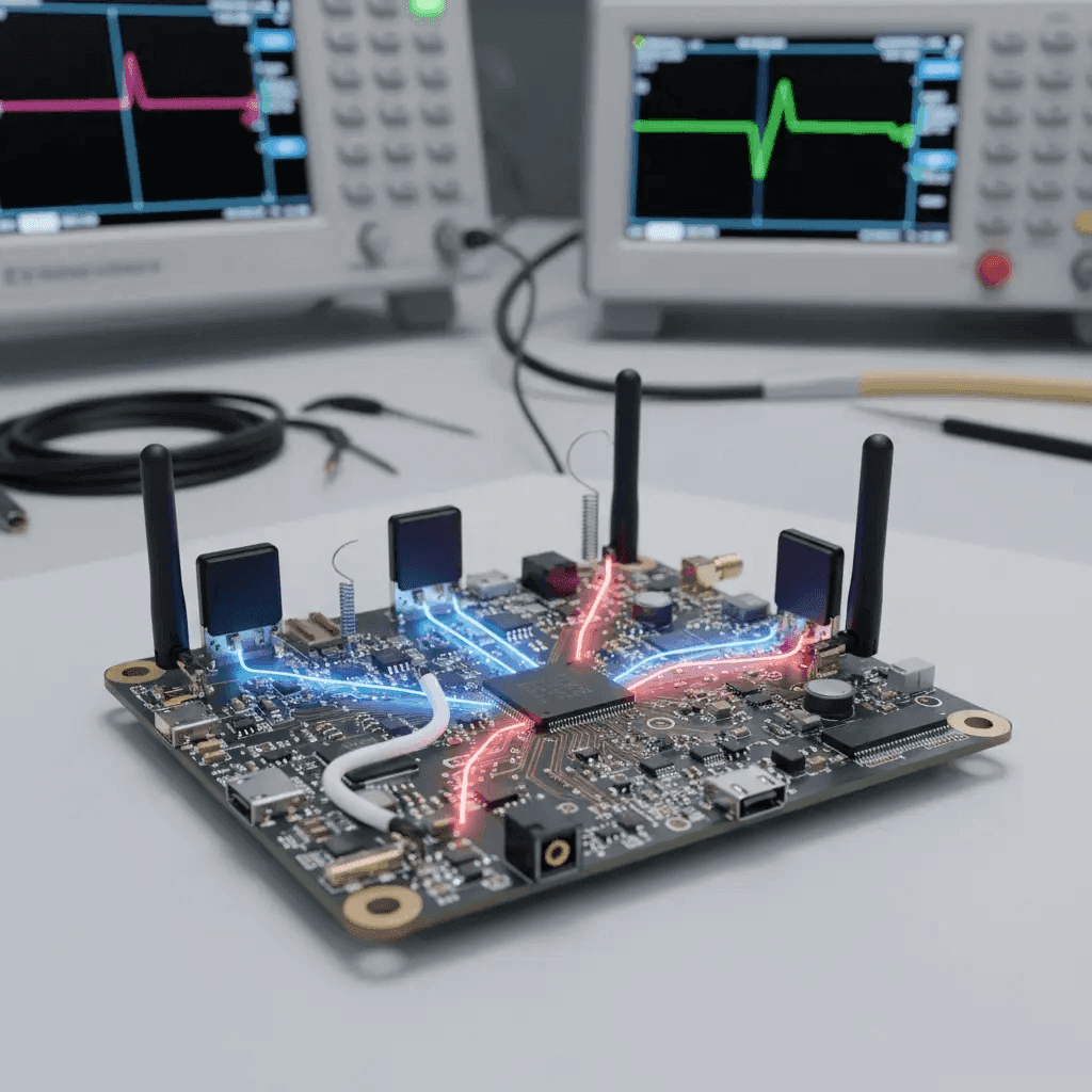
A pigtail concentrates the whole shield current into a single conductor, and that conductor is an inductor. At a few megahertz it makes little difference, and by the time the frequency reaches tens of megahertz the pigtail is the dominant path.
The mistake is easy to make because a pigtail is simple to assemble and easy to repair. It is also invisible on a schematic, so the EMC problem it creates is not visible until the test chamber.
The length of the pigtail is the variable that matters, and the usual guidance is to keep it below a small fraction of a wavelength. In practice, keeping the pigtail shorter than a few millimetres means not having a pigtail at all.
Where a pigtail is the only option available, it should be as short and as wide as possible, with the braid laid flat rather than twisted into a wire. The EMI suppression guide covers the same principle for a board level connection.
360 Degree Clamping
A 360 degree clamp presses the shield against a metal surface around its full circumference. The current is distributed around the ring, the inductance falls by a large factor, and the shield works over a much wider band.
The clamp is usually a metal saddle, a cable gland or a conductive grommet, and it must bond to the chassis metal rather than to paint. A clamp over a painted panel is a clamp over an insulator, and the shield current has nowhere useful to go.
The compression has to be controlled, because a clamp that crushes the dielectric changes the impedance of the cable and a clamp that is too loose has a high contact resistance. A torque specification and a support that prevents the cable from being pulled belong on the drawing.
Where the panel cannot be made conductive, a local masking operation or a separate conductive plate is used. The plate is then bonded to the chassis with a wide, short connection, and the clamp sits on the plate.
Connectors and Backshells
A metal connector shell is part of the shield path, so the connector has to be chosen with the shield in mind rather than with the pin count alone. A plastic shell breaks the path, and a metalised plastic shell has a much higher impedance than a metal one.
The backshell is where the braid is terminated, and it should provide a 360 degree clamp or a crimp ring that is part of the connector system. A backshell that terminates only two or three drain wires is a pigtail in a metal housing.
Inside the enclosure, the cable shield should be terminated at the entry point and not carried to the board, unless the board is the reference for that shield. Carrying a shield into an enclosure and bonding it at the board couples the enclosure interior to the outside field.
Where a shield must also carry a signal reference, the function has to be treated as a circuit and not as a screen. The mixed signal layout in the immunity guide applies to the point where the two meet.

Design and Test
The first design decision is the reference for the shield: the chassis, the board ground, or a separate screen plane. That choice determines where the termination can be made, and it belongs in the interface document rather than in the cable drawing alone.
The mechanical design then has to provide a conductive surface at the entry point, a clamp with a defined compression, and a strain relief that keeps the load off the termination. All three are needed before the electrical performance can be relied on.
Testing is done by measuring the transfer impedance or by injecting a current onto the cable and looking at the voltage that appears on the signal. A comparison between the pigtail version and the clamped version is often the most convincing evidence in a design review.
Where the cable carries a low level signal, a ferrite on the cable outside the shield can add a useful impedance, but it is never a substitute for a proper termination.
FAQ
Is a pigtail ever acceptable? At low frequency and where no other option exists. Above a few megahertz the pigtail becomes the dominant path and the screen loses most of its benefit.
Does the shield have to be grounded at both ends? At both ends where the chassis is the reference at both ends. A single ended shield still works as a screen, but it radiates the common mode current that it collects.
Can a shield be terminated to a painted panel? No. The paint is an insulator, so the panel has to be masked or a separate conductive plate has to carry the clamp.