Eight Circuit Design Misconceptions and What They Cost
Most circuit design misconceptions are not errors of knowledge, they are errors of habit. A rule that was true on one project gets carried to the next one, where the conditions that justified it no longer exist. The eight listed below all share that shape: each one sounds sensible, and each one costs power, board area or money.
Misconception One: A Simple Board Can Be Autorouted
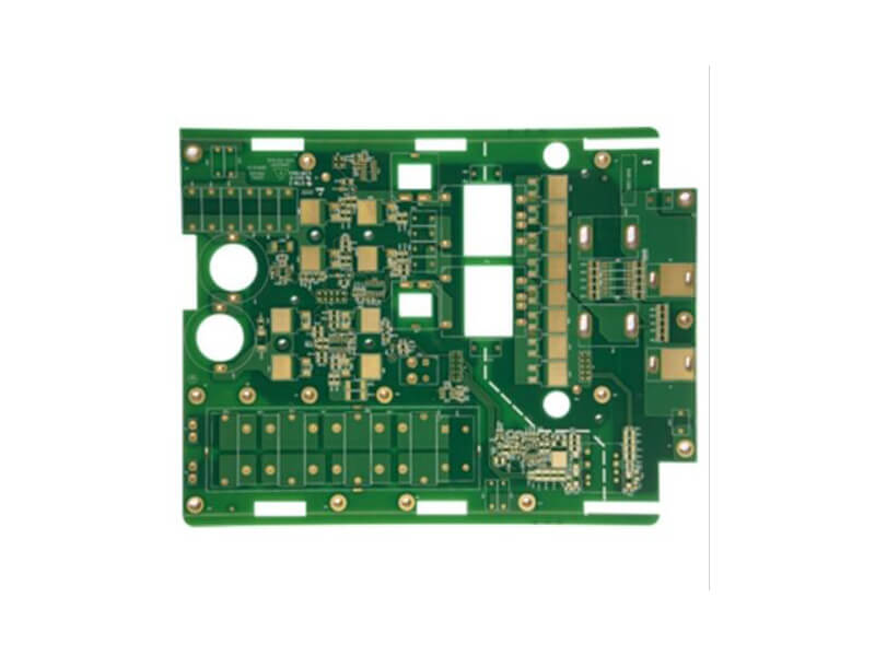
The reasoning is that if the design requirements are low, the routing quality does not matter much, so a thin trace and the autorouter will do. In practice an autorouter consumes more board area than a hand-routed design and produces several times as many vias. On a high-volume product the via count and the trace width are two of the factors that determine fabrication cost, because they affect the drilling tool life and the process yield. A layout that is cheap to design is not automatically cheap to build.
Misconception Two: Every Bus Signal Benefits From a Pull-Up
A pull-up resistor on a plain input draws tens of microamps, which is harmless. The same resistor on a driven signal carries a milliampere or more, because it is fighting the driver whenever the output is low. A system with thirty-two address lines, thirty-two data lines and a bus transceiver in the middle can dissipate several watts in these resistors alone. The rule is that a pull-up resistor belongs where a defined level is required in the absence of a driver, not wherever a designer wants reassurance.
Misconception Three: Unused I/O Pins Can Be Left Floating
A floating input is an input with an undefined level, and a small amount of external noise is enough to make it oscillate. For a complementary metal-oxide-semiconductor input, the power consumption depends on how often the gate flips, so an oscillating unused pin can consume more current than a pin that is doing useful work. Pulling the pin up reduces the current to a few microamps, but configuring the pin as an output is better still, provided nothing else drives the net.
Misconception Four: Spare Logic Is Free
Choosing a larger programmable device than the design needs is often described as leaving room to grow. The power consumption of that device depends on how many flip-flops are actually used and how often they toggle, so two designs in the same part can differ in current draw by a factor of a hundred. Reducing the number of high-speed toggling elements is the most effective way to reduce the consumption, and a device that is mostly idle is not the same as a device that is mostly unused.
Misconception Five: Small Chips Draw Small Current
Current draw is set by the pins, not by the package. A small bus-interface device with no load may draw under a milliampere, but the same part is specified to drive 60 milliamps per output, and a sixteen-bit interface at full load can therefore draw close to an ampère from the supply. The heat largely ends up in the load, but the current still has to come from the board, which means the supply trace, the decoupling and the plane connection all have to be sized for it.
<img src="https://www.gopcba.com/wp-content/uploads/2026/05/家庭壁挂式储能机器-BMS-PCBA.png" alt="Oscilloscope trace showing overshoot and ringing on a digital signal” />
Misconception Six: Tying Chip Select Low Makes Memory Faster
The idea is that holding the chip select active removes a delay from the access path. The cost is that the power consumption of most memories is more than a hundred times higher when the chip select is active than when it is inactive, regardless of the state of the output enable and write enable inputs. Using the chip select to gate access, and keeping the pulse as short as the timing allows, is worth far more than the delay it costs.
Misconception Seven: Overshoot Can Always Be Matched Away
Apart from a small number of specific interfaces, most signals overshoot to some degree, and modest overshoot is acceptable without termination. Full matching is often impossible anyway: a transistor-transistor-logic output may have an impedance below fifty ohms, sometimes as low as twenty, so a matching resistor of that value would demand an unacceptable current and reduce the signal swing to the point of uselessness. Output impedance also differs between the high and low states, so perfect matching is not achievable. The practical target is overshoot that the receiver tolerates.
Misconception Eight: Power Reduction Is Purely a Hardware Problem
Hardware provides the platform, but software decides how often each device on the bus is accessed and how often each signal toggles. Reducing external memory accesses by keeping values in registers or internal cache, servicing interrupts promptly and avoiding unnecessary polling all reduce the current drawn by the same board. A design review that treats power consumption as a hardware-only concern will miss the largest available savings.
Turning the List Into a Design Review
Each of these misconceptions produces a specific, checkable item. Count the vias and review the trace widths before quoting a high-volume price. List every pull-up resistor and ask what defines the level if it is removed. Confirm that unused pins are configured rather than floating. Check the chip-select timing to see whether the pulse can be shortened. Treat these as review questions rather than rules, and the answers will be specific to the board.
Our component tolerance and reliability notes cover how marginal component choices interact with these habits, the design and manufacturing cost reduction material explains how layout decisions appear on a quotation, and the design release checklist provides the review sequence that catches them before fabrication.
Where These Habits Come From
None of the eight misconceptions is unreasonable on its own. Each one is a shortcut that made sense on a previous project, where the volume was low, the bus was short or the power budget was generous. Carrying it forward is what creates the cost. The corrective habit is to write down the assumption behind each decision and check whether the new project still satisfies it. A pull-up that was harmless on a four-bit port becomes a watt of dissipation on a sixty-four-line bus; a device chosen for headroom becomes a heat source when the surrounding logic runs continuously.
Design reviews catch these problems best when they ask about intent rather than about compliance. Asking why a resistor is present, or what happens to a net if a device is not fitted, surfaces the reasoning behind the decision and lets a reviewer judge whether the assumption still holds. That is a more productive conversation than checking a schematic against a rule list, and it is the approach our engineering team takes with customers during design release review.
FAQ
Is autorouting ever acceptable? It is acceptable when the routing is not a cost driver: a one-off prototype, a low-volume instrument or a board whose production cost is dominated by something other than fabrication. It becomes expensive when the product ships in volume, because the extra vias and the wider area are paid for on every unit. Many designers use an autorouter for a first pass and then rework the critical areas by hand, which captures most of the benefit without accepting the whole cost.
How much overshoot should trigger termination? The receiver specification is the only meaningful answer. If the ringing stays inside the input voltage limits and does not cross a threshold more than once, adding termination may cost current and signal swing for no benefit. If the ring crosses a switching threshold, or if the excursion exceeds the absolute maximum rating, termination or a different drive strength is required. Measuring a representative board is more useful than choosing a matching resistor from a table.
What does gopcb see most often in design review? Pull-up resistors on driven buses and floating unused inputs are the two that appear most frequently, and both are inexpensive to correct when they are found at schematic review. We raise them during the engineering review because correcting them after fabrication means a board revision, whereas correcting them before release costs a conversation.