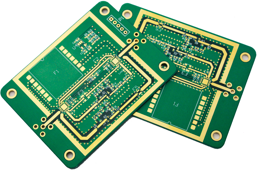
Orientation: Design Rules and Process Limits
A polarized component that is placed the wrong way round produces a board that fails at test and, on some components, a board that fails immediately. The controls that prevent it are a mixture of the design, the data and the inspection, and they have to agree with one another.
Where the Orientation Comes From
The orientation is defined by the footprint, by the package marking and by the tape. The footprint defines the pin one position, the package marking defines where the printed dot or the chamfer is, and the tape defines how the part sits in the pocket.
An error in any of the three produces a placement that is consistent and wrong. Our placement capability notes describe how the machine is set up to reproduce the position.
Footprint and Library Agreement
The library entry for a part carries the rotation, and the rotation has to match the footprint on the board. A library rotation that is ninety degrees out places every instance of that part incorrectly and does so consistently.
The check is a first article inspection against the drawing rather than against the library, because the library is the thing that might be wrong. Our inspection notes describe how the machine is programmed to detect it afterwards.
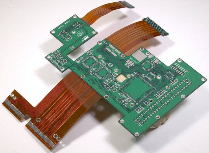
The orientation is confirmed from the package marking, and the marking has to be readable at the machine. A dot that is the same colour as the body or a chamfer that is small relative to the package is difficult to confirm visually.
Where the marking is not readable, the confirmation comes from the reel or from a photograph. That is a slower check and it is the reason a readable marking is worth asking for at the selection stage.
<img src="https://www.gopcba.com/wp-content/uploads/2024/09/Through-Hole-PCB-Assembly2.png" alt="Polarity marker printed beside the footprint” />
The programme carries the rotation and the vision system carries a check of the marking where the machine has one. The two are independent, which is what makes the combination useful: a library error is caught by the vision check and a vision error is caught by the first article.
Where the machine has no vision, the check is the first article and a manual confirmation at the feeder. Both are weaker than a vision system and neither is useless. Our first pass yield notes describe how a polarity escape appears in the data.
The recurring causes are a rotated library entry, a reel that was loaded the wrong way in the feeder, a splice between two parts of the same value and opposite orientation, and a footprint that has no pin one marking so the operator cannot confirm it.
Each has a control. The splice is the one that is most often missed, because the tape looks continuous and the pocket orientation is reversed at the join.
A footprint with a clear pin one marking, a polarity marker in the silkscreen beside the part rather than under it, and a diode or a capacitor placed where the marking will still be visible after assembly.
Those are small changes at the layout stage and they remove a whole class of escape. Our board quality notes describe how the placement is judged at the station.
Acceptance and Its Evidence
Sampling is a compromise between cost and confidence, and the sample size should follow from the failure rate that has to be detected. Where a decision is made by judgement, a boundary sample makes the judgement repeatable between operators and between shifts.
Where a process is at the edge of its capability, the margin should be bought deliberately rather than discovered during production. A record that identifies the operator, the date and the settings is worth more than a record that identifies only the result.
A measurement taken at the wrong point of the process describes the wrong thing, however carefully it is made. Where the supplier and the user both measure the same property, they should agree on the method before the first delivery.
A parameter that is set once and never re verified drifts, and the drift is usually discovered by a defect rather than by the record. The first article confirms that the setup matches the intent, and it is the cheapest point at which a wrong setup can still be corrected.
The cost of verification is small compared with the cost of a field failure, and it is paid at a point where the product can still be corrected. Documentation exists so that a person who was not present can reproduce the work and reach the same conclusion.
Checks Before Release
Consumables have a life measured in cycles, and the replacement point should come from the measurement rather than from a failure. The acceptance criteria should be written before the work starts, so that the decision is made by the specification rather than by the person inspecting.
A result that cannot be reproduced is not a result, and reproducibility should be demonstrated rather than assumed. Handling between operations is part of the process, and the damage it causes is often attributed to the operation that preceded it.
Verification and Records
Where an operation cannot be verified afterwards, it has to be controlled during the operation, and that control has to be visible in the record.
Is AOI enough to catch a polarity error? It catches it where the marking is visible and the programme checks it, and it does not catch a marking that is hidden after assembly.
Can a wrong orientation pass a functional test? It can where the circuit tolerates it, and it usually fails later rather than at the station.
What does gopcb provide for orientation control? We provide library and footprint agreement checked at the first article, readable package markings requested at selection, a vision check where the machine has one, splice orientation controlled at the feeder, pin one marked in the footprint and in the silkscreen, and polarity escapes recorded against the cause.
Points to Confirm at First Article
The checks that matter are the ones performed on the product rather than on a sample kept for the purpose, because a coupon that travels with the panel is the only evidence about that panel. Where a requirement can be measured, it should be measured at the point of manufacture and recorded against the board or the lot it applies to.