Custom Controller PCB: PCB Design, PCB Manufacturing, Benefits & Development Guide
As electronic products become smarter, more connected, and increasingly application-specific, standard circuit boards cannot always satisfy the requirements of modern equipment. Manufacturers and product developers are therefore turning to Custom Controller PCB solutions that are designed around specific electrical, mechanical, functional, and environmental requirements.
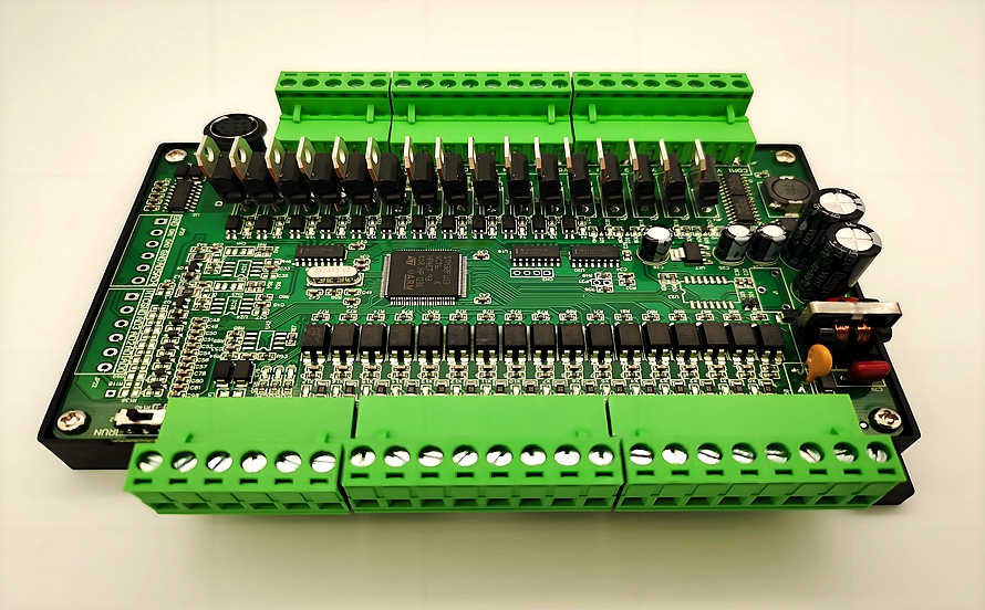
A custom controller PCB can integrate processors, sensors, communication interfaces, power-management circuits, input/output interfaces, and control functions into a compact and application-specific platform. Compared with a general-purpose board, a customized solution provides greater flexibility in circuit architecture, component selection, dimensions, interfaces, and manufacturing requirements.
For applications ranging from industrial automation and consumer electronics to automotive systems, medical equipment, IoT devices, and intelligent control systems, careful PCB Design and reliable PCB Manufacturing are essential for achieving stable performance and long-term reliability.
This guide explains what a custom controller PCB is, its major advantages, key design considerations, development process, and how a professional PCB manufacturer can support customized controller-board development.
What Is a Custom Controller PCB?
A Custom Controller PCB is a printed circuit board specifically designed and manufactured to perform the control functions required by a particular electronic system.
Instead of relying on a standardized development board, engineers can customize the circuit architecture according to the application’s requirements. Depending on the product, the controller PCB may contain a microcontroller or processor, memory, power-management circuitry, sensors, communication interfaces, connectors, driver circuits, and various input/output interfaces.
The PCB essentially serves as the electrical and mechanical platform connecting these functional blocks.
A typical custom controller PCB may be designed for:
- Industrial control equipment
- Motor control systems
- Smart home devices
- IoT equipment
- Automotive electronics
- Medical devices
- Consumer electronics
- Robotics
- Security systems
- Power-management equipment
- Communication equipment
- Measurement and instrumentation systems
The exact architecture depends on the required functions, operating environment, processing requirements, communication protocols, power consumption, and mechanical constraints.
Major Benefits of Custom Controller PCBs
1. Enhanced Performance and Functionality
One of the main advantages of a custom controller PCB is that the circuit can be optimized specifically for the target application.
During PCB Design, engineers can select appropriate components, optimize signal paths, establish suitable power distribution, and allocate board space according to actual functional requirements.
This can help improve:
- Electrical performance
- Signal integrity
- Power efficiency
- Thermal performance
- Processing capability
- System reliability
- Overall product functionality
Rather than including unnecessary circuits and interfaces, a custom board can focus on the functions that the final product actually needs.
2. Cost Efficiency and Scalability
Customization does not necessarily mean higher total product cost. When the circuit is optimized for a specific application, unnecessary components, interfaces, and mechanical features can be eliminated.
This can reduce:
- Component count
- Board area
- Assembly complexity
- Material consumption
- Unnecessary connectors
- System-level integration costs
For production programs, the PCB can also be designed around expected manufacturing volumes and supply-chain requirements.
A prototype may prioritize flexibility and rapid iteration, while a production version can be optimized for cost, manufacturability, component availability, and assembly efficiency.
3. Better System Integration
A controller PCB often needs to communicate with many other parts of an electronic system.
These may include:
- Sensors
- Motors
- Actuators
- Displays
- Communication modules
- Power supplies
- User interfaces
- External I/O devices
- Memory devices
A customized controller board can place these interfaces exactly where they are required.
This improves mechanical integration and can reduce the need for additional adapter boards or unnecessary wiring.
4. Flexible Mechanical Design
Mechanical constraints are often just as important as electrical requirements.
The PCB may need to fit inside a small enclosure, follow a particular mounting pattern, or accommodate connectors at predefined locations.
A custom PCB can therefore be designed with:
- Custom board dimensions
- Irregular board shapes
- Mounting holes
- Connector positions
- Component height restrictions
- Keep-out areas
- Edge requirements
- Flexible or rigid-flex structures where appropriate
This is particularly useful for compact products and equipment with highly constrained internal spaces.
5. Improved Reliability
A well-engineered controller PCB can reduce unnecessary electrical connections and optimize the relationship between components, power distribution, grounding, thermal paths, and mechanical structure.
Reliability can be improved by considering the expected operating environment during both PCB Design and PCB Manufacturing.
Important environmental factors may include:
- Operating temperature
- Humidity
- Vibration
- Mechanical shock
- Electrical noise
- Chemical exposure
- Dust
- Long operating cycles
The PCB material, surface finish, copper thickness, component selection, and protective measures should therefore be selected according to the actual application rather than simply using a standard configuration.
Key Design Considerations for Custom Controller PCBs
A successful controller board requires more than simply placing components on a circuit board. Engineers need to consider electrical performance, mechanical integration, thermal behavior, manufacturability, and long-term reliability.
Component Selection and Placement
Component selection and placement are fundamental aspects of PCB Design.
The location of processors, power components, connectors, sensors, oscillators, memory devices, and high-speed interfaces can significantly affect signal quality and thermal performance.
A practical placement strategy usually considers:
- Functional blocks
- Signal flow
- Power distribution
- Thermal generation
- High-speed signal routing
- Sensitive analog circuits
- Electromagnetic interference
- Connector accessibility
- Manufacturing requirements
Sensitive circuits should be protected from noisy power or switching sections where necessary, while high-current and high-temperature components should have appropriate copper areas and thermal paths.
EMI and EMC Considerations
Electromagnetic interference (EMI) and electromagnetic compatibility (EMC) are important considerations for controller boards.
Poor layout can result in unwanted noise, signal coupling, electromagnetic emissions, or susceptibility to external interference.
Depending on the application, designers may use techniques such as:
- Appropriate grounding strategies
- Continuous reference planes
- Controlled return paths
- Careful separation of noisy and sensitive circuits
- Proper power decoupling
- Shielding
- Filtering
- Differential signaling
- Optimized high-speed routing
EMI/EMC should be considered early in the design rather than treated as a final-stage correction.
Power Integrity and Signal Integrity
Controller boards increasingly contain processors, communication interfaces, switching regulators, sensors, and high-speed interfaces.
This makes power integrity and signal integrity important parts of the overall design.
Designers should consider:
- Power distribution network impedance
- Decoupling capacitor placement
- Ground-plane structure
- Trace impedance
- Return-current paths
- Crosstalk
- Signal rise/fall times
- High-speed interface requirements
For demanding designs, stackup planning and impedance-controlled routing may be necessary.
Custom Dimensions and Interfaces
One of the most important advantages of a custom controller PCB is that the board can be designed around the final product.
The design can accommodate:
- Custom dimensions
- Different board shapes
- Specific connector types
- Mounting-hole patterns
- Edge connectors
- Cable interfaces
- Display interfaces
- Sensor connections
- Communication interfaces
This allows the PCB to function as an integral part of the product rather than as a generic electronic module.
Material Selection
PCB material selection 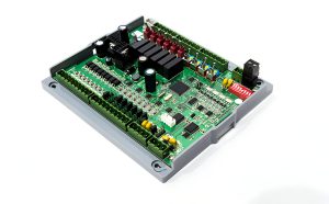 directly affects electrical, mechanical, thermal, and reliability characteristics.
FR-4 is widely used for general-purpose controller boards because it provides a practical balance of cost, electrical insulation, mechanical strength, and manufacturability.
However, specialized applications may require other materials or constructions.
Material selection may depend on:
- Operating frequency
- Signal-loss requirements
- Operating temperature
- Thermal requirements
- Mechanical requirements
- Dielectric properties
- Reliability requirements
- Cost targets
For high-speed or RF controller applications, specialized low-loss laminates may be considered when conventional FR-4 cannot provide the required electrical performance.
Custom Controller PCB Development Process
Developing a custom controller board normally involves several interconnected stages.
1. Define System Requirements
The first step is to clearly define what the controller PCB must accomplish.
Engineers should establish:
- Functional requirements
- Input and output requirements
- Processing requirements
- Power requirements
- Communication protocols
- Operating voltage
- Environmental conditions
- Mechanical dimensions
- Expected production volume
- Applicable regulatory requirements
A clear specification helps prevent major changes later in the development cycle.
2. Create a Functional Block Diagram
After defining the requirements, engineers can divide the system into functional blocks.
For example, a controller PCB may contain:
Power Input → Power Management → Processor → Communication → Sensors → Actuators → I/O
The block diagram provides a high-level view of how the major sections interact before detailed circuit design begins.
3. Develop the Schematic
The next stage is schematic development.
The schematic defines electrical relationships between components and provides the foundation for the subsequent PCB layout.
Engineers should verify:
- Component values
- Power connections
- Signal paths
- Interface compatibility
- Protection circuits
- Clock circuits
- Reset circuits
- Communication interfaces
- Power sequencing where required
A schematic review before layout can help identify design issues at an early stage.
4. Perform PCB Layout
Once the schematic has been verified, engineers can begin the physical PCB Design.
This stage involves:
- Component placement
- Layer-stack planning
- Routing
- Ground-plane design
- Power distribution
- Via selection
- Thermal management
- Clearance checking
- Design-rule checking
High-speed, analog, power, and digital circuits may require different routing strategies.
The layout should also consider the requirements of downstream PCB Manufacturing so that the final design can be produced consistently.
5. Design for Manufacturing and Assembly
DFM and DFA reviews are important before production.
The design should be checked for:
- Minimum trace width and spacing
- Drill sizes
- Annular rings
- Component spacing
- Solder-mask clearance
- Silkscreen placement
- Panelization
- Assembly accessibility
- Manufacturing tolerances
Designing with manufacturing capabilities in mind can reduce unnecessary redesigns and improve production yield.
6. Build and Test a Prototype
Prototype production transforms the digital design into a physical controller board.
The prototype can be evaluated for:
- Functional performance
- Electrical characteristics
- Communication reliability
- Thermal behavior
- Mechanical fit
- EMI/EMC performance
- Software-hardware interaction
- Connector compatibility
Testing at this stage can reveal problems that may not be obvious in simulation or schematic review.
7. Verification and Design Optimization
After prototype testing, engineers may need to modify the PCB.
Typical improvements can include:
- Component changes
- Routing optimization
- Power-distribution improvements
- Thermal improvements
- EMI reduction
- Connector relocation
- Mechanical adjustments
- Firmware-related hardware changes
Several prototype iterations may be required for complex products.
8. Move to Production
After the controller PCB has passed functional and reliability verification, the design can proceed to volume PCB Manufacturing and PCB assembly.
Production documentation may include:
- Gerber or ODB++ files
- Drill files
- PCB specifications
- Stackup information
- Bill of materials (BOM)
- Pick-and-place files
- Assembly drawings
- Test requirements
Close communication between the design team and manufacturing partner helps ensure that the production version matches the validated prototype.
Custom Controller PCB Manufacturing Considerations
A custom design is only useful when it can be manufactured consistently.
During PCB Manufacturing, manufacturers may need to consider the board’s layer count, copper thickness, material, finished thickness, surface finish, drilling technology, impedance requirements, solder mask, and other specifications.
For more complex controller boards, manufacturing may also involve:
- Multilayer lamination
- Controlled-impedance fabrication
- Microvias
- Via filling
- Fine-pitch routing
- HDI technology
- Advanced surface finishes
- Electrical testing
- AOI inspection
- X-ray inspection for assembled boards
Therefore, designers should involve the PCB manufacturer early when the design includes demanding manufacturing requirements.
How Kingda Supports Custom Controller PCB Projects
For companies developing application-specific electronic products, working with an experienced manufacturing partner can simplify the transition from design to production.
Kingda can support customized PCB projects by combining PCB fabrication and PCB assembly capabilities with engineering-oriented manufacturing support.
Depending on project requirements, a custom controller PCB program can involve:
- Prototype PCB manufacturing
- Multilayer PCB manufacturing
- PCB assembly
- SMT assembly
- Through-hole assembly
- Component sourcing
- DFM review
- Electrical testing
- Quality inspection
- Production support
When selecting a supplier, customers should evaluate manufacturing capabilities, quality systems, component sourcing, testing capability, communication efficiency, production capacity, and experience with similar applications.
Common Applications of Custom Controller PCBs
Custom controller boards can be used across a wide range of industries.
Industrial Automation
Industrial controllers may integrate sensors, communication interfaces, motor drivers, and I/O circuits to control machines and production equipment.
Automotive Electronics
Automotive controller boards may be used in body electronics, lighting, power management, sensor interfaces, and other vehicle systems. Automotive applications typically require careful consideration of temperature, vibration, reliability, and EMC requirements.
IoT Devices
IoT controller PCBs may combine processors, wireless communication modules, sensors, memory, and power-management circuits in a compact form factor.
Medical Equipment
Medical electronic systems often require highly reliable control and monitoring circuits. PCB design must account for electrical performance, reliability, manufacturability, and applicable regulatory requirements.
Robotics
Robotic systems can use custom controller PCBs to integrate processors, motor control, sensors, communication interfaces, and power-management functions.
Consumer Electronics
Smart appliances, wearable products, entertainment equipment, and other consumer products can benefit from custom PCB solutions that reduce size and integrate multiple functions into a single board.
How to Choose a Custom Controller PCB Manufacturer
Choosing the right manufacturing partner is an important part of the development process.
Before selecting a supplier, consider the following factors:
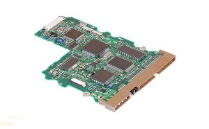
- PCB manufacturing capabilities — Verify layer count, material options, copper thickness, surface finishes, HDI capability, and other technical capabilities.
- PCB assembly capability — Check SMT, through-hole, mixed-technology assembly, component sourcing, and inspection capabilities.
- Engineering support — Determine whether the manufacturer can provide DFM and production engineering feedback.
- Testing capability — Evaluate AOI, electrical testing, X-ray inspection, functional testing, and other relevant methods.
- Quality management — Review applicable quality systems and certifications for the target application.
- Production scalability — Make sure the supplier can support the project from prototype quantities through production.
- Communication and documentation — Clear communication is especially important for custom boards with complex specifications.
Conclusion
A Custom Controller PCB provides a flexible way to build electronic systems around specific functional, electrical, mechanical, and environmental requirements. Unlike generic development boards, customized controller boards can be optimized for the exact application, including component selection, board dimensions, interfaces, power architecture, signal routing, thermal management, and manufacturing requirements.
The success of a controller board depends on more than the schematic itself. Effective PCB Design, appropriate material selection, EMI/EMC planning, DFM analysis, prototype testing, and reliable PCB Manufacturing all contribute to the final product’s performance and reliability.
As technologies such as AI, IoT, 5G, industrial automation, and intelligent control continue to develop, demand for application-specific controller electronics is likely to remain strong. By combining sound engineering principles with a capable manufacturing partner such as Kingda, product developers can move from concept and prototype to reliable production more efficiently.
Article Summary
A custom controller PCB is a purpose-built circuit board designed around the specific requirements of an electronic system. Its main advantages include design flexibility, system integration, performance optimization, scalability, and application-specific reliability. A successful project requires a structured process covering requirements definition, schematic design, PCB layout, DFM, prototype development, testing, optimization, and production. Selecting an experienced PCB manufacturing and assembly partner is also essential for transforming a customized controller design into a stable and manufacturable product.