



Building a Drill Table for Fabrication
Why a Drill Table Exists
The drill table is the summary of every hole in the design, grouped by size and by function, and it is the document the fabricator uses to set up the drilling programme. Without it, the shop derives the hole sizes itself, and the derivation may not match what the design intended: a connector hole that needed a finished diameter of 1.0 mm may be drilled so that the plated hole is 1.0 mm, or so that the drill is 1.0 mm, depending on how the note was read. The table removes that ambiguity by listing each hole size, its function and its tolerance.
Finished Versus Drill Diameter
The first decision is which diameter to tabulate. A finished diameter is what the component needs; a drill diameter is what the machine uses. Because plating closes the hole by roughly 0.04 to 0.05 mm in diameter for a standard barrel, the two differ, and the difference matters most where the tolerance is tight. The convention that causes fewest problems is to tabulate the finished hole size with its tolerance and to let the fabricator add the plating allowance, since only the fabricator knows the plating thickness that will be deposited. Where a specific drill diameter is required, for instance for a tooling hole that will not be plated, the table should say so explicitly and mark the hole as non-plated.
Grouping Hole Sizes
Every distinct drill size is a separate tool and a separate setup, so reducing the number of sizes reduces cost and time. Where a design has a 0.30 mm via and a 0.32 mm via, they are two tools for no benefit; rounding them to one size costs nothing electrically and saves a tool change. The grouping should be done deliberately, with a note that two nominal sizes have been merged, so that the fabricator does not wonder whether the difference was intentional. On the other hand, sizes that look similar but have different functions, such as a via and a mounting hole, should never be merged, because their tolerances differ.
Plating and Tolerance Columns
The table should record, for each size, whether the hole is plated, the tolerance on the finished diameter, and any special requirement such as a controlled depth, a press-fit fit, or a castellation. The plating column is essential: an unplated hole is drilled at its finished size and needs no allowance, and confusing the two produces a hole that is either too large or too small. The tolerance column is what allows the shop to know whether a size is critical or nominal, and it should be realistic, since a tolerance tighter than the process can hold simply generates a conversation later.
Vias in the Table
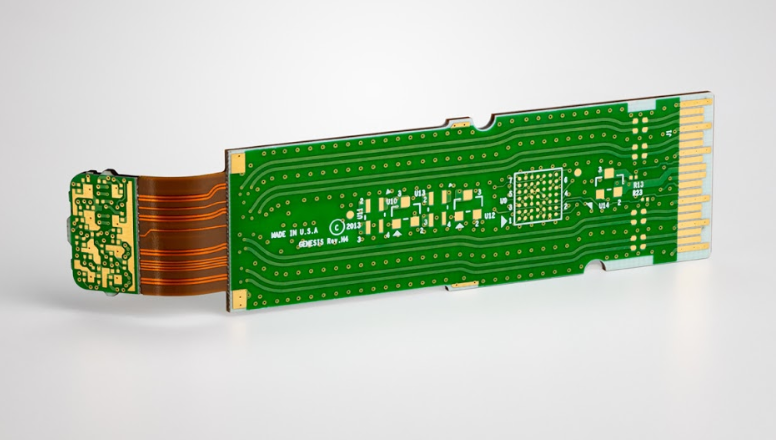
Vias are holes and belong in the table, usually grouped by their diameter and their type: through, blind, buried, microvia, or a via that will be backdrilled. Where the design has several via types, the table is the natural place to record the aspect ratio and the fact that some are filled, since the fabricator needs to know which holes go through which process. Backdrilled vias should be listed with their residual stub requirement, and microvias with the layer they connect, because those are properties of a specific hole rather than of the board.
Slots and Routed Features
Slots and routed openings are not drills but they are machined features and they belong in the same summary, with their width and length. A slot that is narrower than the smallest router bit available is a design error that the table makes visible. The table should also record any hole that must be countersunk or counterbored, with the reference to the mechanical note, so that the drilling and the machining operations can be planned together rather than discovered separately.
Common Errors
The errors that recur are tabulating drill sizes while calling them finished sizes, forgetting a via size, listing a tolerance that is tighter than the process, mixing plated and non-plated holes of the same nominal diameter without marking them, and omitting the special holes such as tooling and mounting holes because they were added late. A table generated automatically from the layout data avoids most of these, provided the hole attributes are correct in the data, which is why the attributes matter more than the table itself.
Documenting Special Holes
The holes that cause trouble are rarely the ordinary vias; they are the ones added late or specified in a note rather than in the data. A tooling hole that only exists on the panel, a mounting hole that has to be non-plated, a press-fit hole with a tight finished tolerance, a castellation, a hole that must not be plated because it will take a screw: each of these needs to appear in the same table as everything else, with its function stated. A note on a drawing is easy to miss when a shop is working from the data, whereas a row in the drill table is part of the data. Where a hole has a mechanical function, the table should also reference the mechanical drawing, so that the two documents cannot drift apart. The habit of listing every hole in one place is what makes the fabrication package self-consistent, and self-consistency is what removes the follow-up questions that delay an order.

FAQ
Should the drill table list drill or finished diameters? Finished diameters with their tolerances, unless a specific drill size is required, in which case say so and mark the hole as non-plated if applicable.
How much does plating close a hole? Around 0.04 to 0.05 mm in diameter for a standard barrel, more for heavy plating.
Why group hole sizes? Because each distinct size is a separate tool and setup, and merging near-identical sizes saves time without affecting the design.
Do vias belong in the table? Yes, grouped by type and diameter, with the aspect ratio and any filling or backdrilling requirement.
What is the most common error? Confusing drill and finished diameters, which produces holes that are consistently the wrong size.
Conclusion
The drill table is a small document that prevents a large class of manufacturing errors, so it should list finished sizes, tolerances, plating status and special requirements, with vias and machined features included. Generate it from the layout data where possible, and check the hole attributes rather than the table alone. Drilling capability is described under PCB capabilities, the process behind the tolerances in PCB manufacturing, and the pad sizes that accompany each hole in PCB design and layout. A complete fabrication package is the normal basis for a prototype PCB assembly order in 2026.


