EMC Design Principles: Loop Area, Grounding and Stackup
Electromagnetic compatibility is often presented as a list of prohibitions, which makes it hard to remember and harder to apply. The underlying physics is much smaller: current radiates, loop area determines how efficiently, and common mode current is what leaves the board on cables. Almost every practical EMC design rule is a consequence of those three statements, and the principles below follow from them.
Differential and Common Mode Current
Every circuit carries two kinds of current. Differential current is the useful signal: it flows out along one conductor and back along another, with equal magnitude and opposite direction. Common mode current flows in the same direction on all conductors of a cable or a group of traces, and it returns through some other path, often the chassis or the ground reference of the system.
Both radiate, but not equally. The field of a differential current is confined to the loop it encloses, and outside that loop the fields from the two conductors cancel. The field of a common mode current adds rather than cancels, so a very small common mode current can radiate more than a large differential one.
Why Common Mode Dominates Emissions
Equipment emissions are usually common mode by a wide margin, and incoming interference is usually common mode as well. The reason is the geometry: a differential loop on a board is small, whereas the common mode path is often a cable several metres long, which is an efficient antenna.
Common mode current is not harmless in itself, because a common mode voltage on a cable does not disturb the differential signal that the receiver is looking at. The damage happens when common mode energy converts to differential, because then it appears directly in the signal. Conversion occurs wherever the two conductors of a pair see different impedances, which is why symmetry in the layout matters.
Loop Area and Differential Radiation
The radiated field from a differential current is proportional to the area of the loop it encloses. On a board, that loop is the signal trace plus its return path, and the return path is usually the plane directly underneath rather than any conductor drawn by the designer.
The practical consequence is direct: keep the return path adjacent to the signal and the loop is small. Move the signal across a plane split and the return is forced to detour, which can multiply the loop area by an order of magnitude without any change to the artwork of the trace itself.
Reference Continuity Comes First
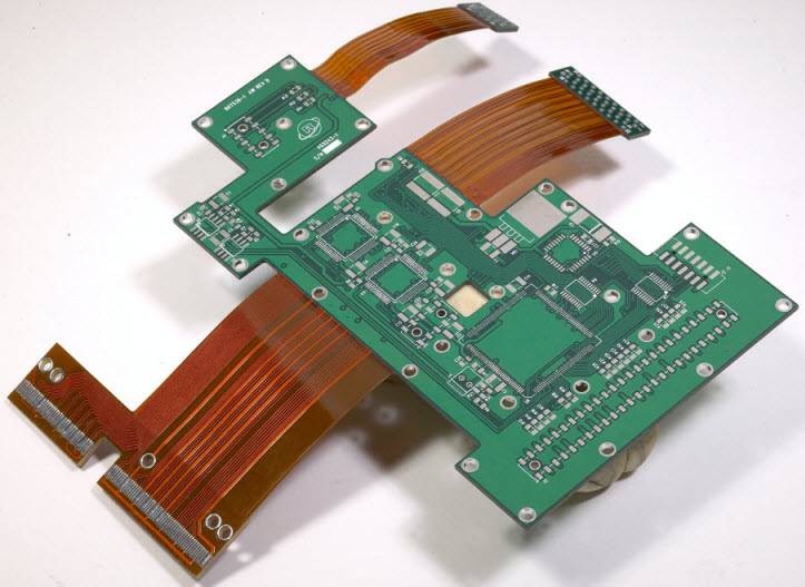
The first EMC principle in practice is that every high-speed signal must have a continuous reference plane beneath it for its entire length, and that the reference must be the same plane throughout. A layer change requires a stitching via next to the signal via so that the return current can change planes too.
This single rule prevents more emissions than any filter. It also explains why a board laid out with a broken ground plane is so difficult to fix later: the problem is distributed along the traces rather than concentrated in a component that can be changed.
Choosing the Layer Count and the Stackup
When the clock exceeds roughly 5 MHz, or when the fastest edge is shorter than about 5 ns, a multilayer board is normally required, because only a multilayer stack provides a plane for the return current to follow. Below those thresholds a two-layer board can work if the critical signals are given a ground pour and a guard.
Within a multilayer stack, the critical signals should be routed on the layer adjacent to a solid ground plane or, better, between two ground planes. Critical nets are the clock, the buses, the interface signals, the radio paths, the reset line and the chip selects, because they are either strong radiators or sensitive receivers. EMI suppression design principles lists the layout measures that follow from this.
Guard Traces and Ground Pour
On a single-layer board, or in a region of a multilayer board where a plane is not available, a guard trace either side of a critical signal provides a return path and reduces coupling to its neighbours. The guard has to be connected to ground at intervals; a floating guard is worse than nothing because it couples noise from one line to the next.
On a two-layer board the equivalent measure is a ground pour with a via fence along the critical route, so that the reference is continuous in the plane of the traces. Neither measure is as good as an adjacent plane, but both are useful when the stack does not allow one.
Plane Edges and Pullback
A power plane should be inset relative to the ground plane it references by roughly 5 to 20 times the dielectric thickness between them. The purpose is to keep the fringing field at the plane edge inside the board so that the perimeter does not become a slot radiator.
The related rule is that every routing layer should sit inside the projection of its reference plane. If the plane ends before the routing does, the field at the edge is unbounded, the loop area grows and the trace radiates. Power plane splitting rules covers how to divide a plane without creating those unbounded edges in the middle of the board.
Connectors, Cables and Filters
The edge of the board and the cable that leaves it are where common mode current escapes. Signals that leave the board should be filtered close to the connector, not close to the source, and the return for the filter must be a short, direct connection to the ground plane.
Where a cable shield is used, its effectiveness depends on how it is terminated. A shield connected through a long pigtail provides almost no benefit at high frequency; a shield bonded to the chassis around its circumference works. This is a mechanical design decision as much as an electrical one, and it belongs in the review.
Keeping the Fast Edges Local
The highest-frequency energy on a board is generated where the current changes fastest, which is at switching nodes in power converters and at the outputs of fast drivers. Keeping those areas small, keeping the loops tight and keeping them away from connectors reduces the excitation that everything else has to tolerate.
A useful habit is to place the noisiest circuit in the middle of the board rather than at the edge, so that any coupling that does occur is attenuated before it reaches the perimeter. Ground current and harmonic distortion explains how the return path interacts with the signal in ways that are not obvious from the schematic.
FAQ
Is common mode current always a problem? It is a problem when it leaves the board on a cable or when it converts to differential mode in a sensitive circuit. On a well-designed board, most of it stays inside the enclosure.
Does a guard trace work without a ground plane? It works if it is grounded at intervals and sized so that it does not act as a resonant stub. A single connection at one end is not sufficient.
Why is a plane split worse than a longer trace? Because the return current has to detour around the split, and the loop area that results is much larger than the extra length of the trace itself.