Fiducial: Design Rules and Process Limits
A placement machine does not know where the board is. It knows where it thinks the board is, based on the fiducials it can see, and every subsequent placement is referenced to that measurement. Poor fiducials therefore produce a systematic offset that affects every component, and the offset is often misdiagnosed as a machine calibration problem. This article covers how fiducials are designed, where they belong and how the alignment is verified.
What a Fiducial Has to Do
A fiducial is a shape that the vision system can find reliably and locate precisely. To do that it must have contrast against its surroundings, a size that matches the camera resolution and a clear area around it so that the search does not lock onto a neighbouring feature. Its position then defines the coordinate system for everything else.
The system measures two or more of them and solves for translation, rotation and, on some machines, scale. Two marks define translation and rotation, three add scale, and more marks allow an average that reduces the effect of a local error. The number used should match the accuracy the product needs rather than the machine default.
Shape, Size and Contrast
A circle, a square or a cross are all used, and the choice depends on how the vision algorithm detects the centre. A round mark gives a rotation independent centre, while a cross or a square corner gives a sharper edge for some algorithms. Whichever is chosen, the mark should be the same across the product so that one set of parameters works.
Contrast is produced by the copper and the mask together. A fiducial is normally an area of exposed copper with a defined clearance, which gives a bright feature against a dark mask. A mark covered by mask has much lower contrast and is a common cause of a vision failure, particularly after coating or on a dark mask colour.
<img src="https://www.gopcba.com/wp-content/uploads/2023/05/f7579e_634a5e092d5149e48cc996e014e7ddb8_mv2_d_2800_1560_s_2.png" alt="Fiducial mark on a PCB viewed by a machine vision camera” />
Clearance and Keep Out
The clearance around the mark must be free of copper, mask features, silkscreen and, most importantly, components and their shadows. A fiducial near a tall component may be visible on the machine that places that side of the board and invisible to a camera at a different angle, and a fiducial partly covered by a silkscreen legend produces an unpredictable centre.
The keep out area should be defined in the library for the fiducial so that it is enforced during placement. It should also account for the process, because a fiducial that is clear on the bare board may be covered by a stencil or by a coating later. Where the same mark must serve several operations, its clearance has to satisfy all of them.
Panel and Local Fiducials
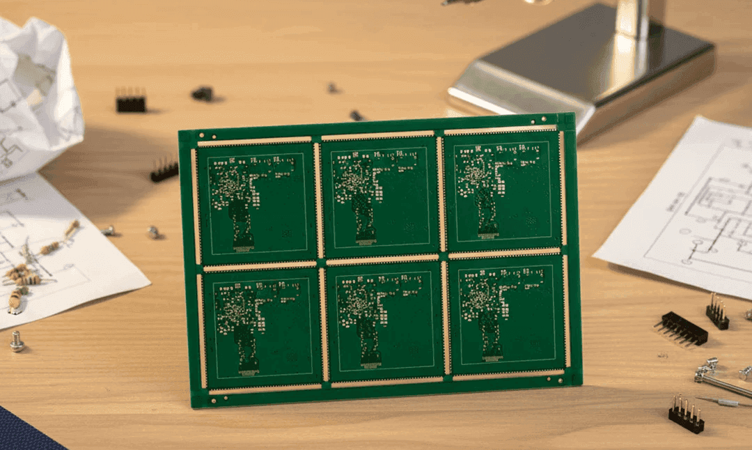
Panel fiducials are placed on the panel rail or in a dedicated area and are used to align the whole panel. Local fiducials are placed on each individual board and are used to correct for the distortion of that board within the panel. Both levels are needed when the panel is large or when the board is fine pitch.
The reason is that a panel is not rigid and does not stay flat and uniform. Lamination and reflow both change its dimensions, and the change is not the same everywhere. A global alignment based on panel marks leaves a residual error at the far corners, and local marks correct it. The design implications for the panel are covered in panel utilization and array layout.

Fiducials for Other Processes
Printing, placement, inspection and test all need alignment, and each has its own requirements. A printer may use the same fiducials as the placement machine, or it may use the stencil aperture pattern, while an inspection system may prefer a mark with a different size because of its camera resolution. Where the marks differ, each should be present and identified.
Test fixtures use tooling holes rather than fiducials, but the same principle applies: the reference must be unambiguous and consistent. A board that has both a fiducial and a tooling hole should have them related in the design data so that a comparison between processes is meaningful. The design conventions used for those features are the same as for other fabrication features, described in PCB fabrication notes.
Common Alignment Errors
The most common error is a fiducial that is too close to the board edge, where it is partially covered by the conveyor or by a rail. The second is a fiducial placed under a connector or a tall component, where it is occluded. The third is a mark with insufficient contrast, which produces a vision failure or, worse, an intermittent lock onto the wrong feature.
A fourth is asymmetric placement. If the marks are clustered on one side of the board, the rotation solution amplifies any measurement error at the far corner. The marks should be spread as widely as the board allows, ideally at opposite corners, so that a small error in each produces a small error in the solution.
Designing a Fiducial Into a Dense Board
Space is the usual objection, and it is usually surmountable. A fiducial is small, and the keep out area can often be shared with an existing feature such as a tooling hole or a component free zone under a connector. The mistake is to place a mark in whatever gap remains after the layout is complete, because those gaps are often the ones that get covered by a component in the next revision.
The fiducial should be one of the first features placed, along with the tooling holes and the panel outline. Placing them early makes the keep out areas real constraints rather than objections, and it prevents the last minute compromise that produces marginal contrast or a partial occlusion. The same discipline applies to the test point design that provides the fixture access, since both are process features that depend on being reserved before the layout fills up.
Verification and Troubleshooting
Verification is straightforward. Measure the position of a set of components relative to the board datum on a sample, and compare the result with the placement machine report of the fiducial positions. A difference that grows with distance from the marks indicates a rotation or scale error, while a constant offset indicates a machine or program issue.
The gopcb assembly group records fiducial identification failures as a separate defect category, because they cause a whole board to be misplaced rather than one component. Tracking that number over time shows whether the marks are degrading, which happens when a coating, a cleaning residue or a handling mark reduces the contrast, and it gives the evidence needed to change the design rather than to keep adjusting the machine.
FAQ
How big should a fiducial be? Large enough for the camera to resolve it reliably at the working field of view, and consistent across the product. The machine supplier guidance is the starting point.
Can a fiducial be covered by solder mask? It should not be, because the contrast is much lower. An exposed copper mark with a clear ring is the reliable choice.
How many fiducials are needed? Two for translation and rotation, three or more where the panel distorts or where scale must be corrected.