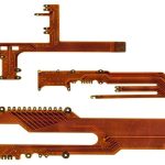
Flexible PCBA for Foldable Phones: Bend Life and Stack-Up
A foldable phone puts a flexible circuit through a mechanical duty cycle that no other consumer product demands. The interconnect that crosses the hinge has to fold and unfold thousands of times over the life of the device, in a space only a few tenths of a millimetre thick, while carrying high-speed display signals and power. Designing that assembly is a mechanical and materials problem as much as an electrical one.
This article covers how a flexible PCBA for a folding device is designed, what determines its bend life, and the rules that keep the conductors intact through the fold cycle.
What the Fold Region Has to Do
The fold region carries the signals between the two halves of the device: the display link, the camera links, the power rails and the sensor connections. It has to do that while the device is folded, half folded and flat, in an enclosure whose thickness is measured in fractions of a millimetre.
That combination means the flex cannot simply be made thicker to gain robustness. Every micron of thickness increases the strain on the outermost copper for a given bend radius, so the design is a search for a thin stack that can still carry the required signals and survive the required number of cycles without the copper cracking. The constraint is unusual: in most products the flex is the cheap part, and here it is one of the most demanding components in the device.

Static and Dynamic Flexing
The distinction between a static and a dynamic flex determines almost everything else. A static flex is formed once during assembly and never moves again; the copper only has to survive that single forming operation. A dynamic flex moves in service, and the copper sees a strain cycle every time the device is opened or closed.
A foldable phone has both. The display flex is dynamic, moving with every fold, while the connections to a battery or a side-mounted sensor may be static. The two should not be built to the same specification, because applying dynamic rules everywhere raises the cost of the parts that never move, and applying static rules to the fold region guarantees an early failure.
Layer Stack for a Bending Area
The stack in the fold region is built from the thinnest available materials. A common construction is a single flexible core with conductors on both sides, using a thin polyimide base and an adhesiveless bond, covered on both faces so that the copper sits close to the neutral axis of the bent stack.
Symmetry is the governing principle. If the copper on one side is further from the neutral axis than the copper on the other, that side sees more strain and will crack first. The coverlay thickness, the base thickness and the adhesive layers all contribute, and the arrangement should be chosen so that the tensile and compressive strains are balanced. The coverlay construction rules describe how the protective layers affect that balance.
Copper Type and Trace Direction
Rolled annealed copper is used in a dynamic flex rather than electrodeposited copper. Rolled copper has a large grain structure that accommodates repeated strain, while the smaller grains of an electrodeposited deposit are more prone to cracking along the grain boundaries after a few thousand cycles.
The direction of the traces relative to the bend line matters as much as the copper type. Conductors running perpendicular to the bend line experience the strain along their length and survive; conductors running parallel to the bend line concentrate the strain across their width and crack. Where a trace has to run along the fold, it should be as narrow as the current allows and placed as close to the neutral axis as possible, and the design should treat every such trace as a reliability risk. The rigid-flex construction notes cover the same principle in a broader context.
Bonding and the Neutral Axis
The adhesive layers in a dynamic flex are part of the mechanical design. A thick adhesive layer adds thickness without contributing to the electrical function, and because it is further from the neutral axis than the copper, it increases the bending stiffness in a way that raises the strain on the coverlay. Adhesiveless construction removes that layer entirely and is the standard approach for a fold region.
The neutral axis position can be estimated from the thickness and the modulus of each layer, and the copper should be placed as close to it as the construction allows. In practice that means the total thickness of material above and below the conductor layers should be nearly equal, and any asymmetric feature, such as a stiffener or a shield layer on one side only, should be kept out of the region that bends.
Connectors and Stiffeners
The ends of the flex carry connectors, and a connector cannot be soldered to a thin flexible tail without support. A stiffener bonded to the back of each connector area provides the rigidity the connector needs and brings the tail to the thickness the connector expects.
The stiffener must end well before the bend region begins, and the transition between the stiffened area and the flexible area has to be gradual enough that the strain spreads out rather than concentrating at the stiffener edge. The stiffener placement rules describe the geometry, and on a folding device the transition zone is usually longer than on a conventional flex, because the cyclic load is far greater.
Assembly, Test and Rework
The fold region cannot be reworked. Once the assembly is closed, the flex is inaccessible, and a rework operation on a nearby joint risks damaging the conductors even if it does not touch them directly. That means the flex has to be tested before it is installed, and the assembly process has to be arranged so that the flex is the last component to be placed and the first to be protected.
Test coverage should include a continuity check of every net after the fold test, because a conductor that has been partially cracked may still conduct when flat and fail when bent. A functional test performed while the device is folded and unfolded is more informative than a static test, and it is the only way to catch a marginal trace before the product ships, because a cracked conductor can pass a static continuity check and fail on the first fold in the customer’s hand.
FAQ
How many fold cycles should the flex survive? The figure comes from the product specification and is usually expressed with a large margin over the expected usage. The design margin should also account for the fact that the flex is folded during assembly and during any service operation.
Why is rolled copper used in the fold area? Because its larger grain structure tolerates repeated bending far better than an electrodeposited deposit of the same thickness. The difference is measurable in cycle tests and it is not compensated by adding thickness.
Can the fold region carry high-speed display signals? Yes, and it usually does. The pair geometry and the impedance have to be maintained through the bending area, and the materials must give a stable dielectric constant, because a change in impedance during the fold appears as a reflection.