Flexible Printed Circuits in Electric Vehicle Harnesses
A modern vehicle contains more copper than most people expect, and a growing share of it is not round wire. A flexible printed circuit replaces a bundle of individual wires with a flat laminated conductor pattern that follows the shape of the space it occupies, can carry the same signals, and can be terminated in a single connector instead of dozens of crimped contacts.
The shift has been driven by the electrification of the powertrain and by the density of electronics in the cabin. Battery monitoring, cell balancing, module interconnection, seat and door harnesses and the sensor chains around the vehicle all use flexible circuits where a wire bundle would once have been the default. Understanding where the technology fits, and where it does not, is the subject of this article.
Why Flexible Printed Circuits Replace Wire Harnesses
A wire harness is assembled from many separate conductors that are cut, stripped, crimped and then bundled. Every one of those operations is a source of variation, and every crimp is a potential intermittent fault. A flexible printed circuit is made as a single part with the conductor pattern defined photolithographically, so the geometry is repeatable and the number of terminations is reduced to the connectors at each end.
Weight and volume are the other arguments. A flat cable occupies the height it needs and nothing more, which matters when it has to pass through a hinge or along the inside of a battery pack. Copper weight can be graded, so a high current conductor and a signal conductor can coexist on the same part without the weight penalty of using heavy gauge wire for everything. Both effects are strongest in high voltage battery monitoring, where the number of channels is large.
Battery Monitoring and Cell Connections
Battery management systems measure the voltage of every cell group, and in a pack with a hundred channels that means a hundred pairs of conductors running from the monitoring board to the cell terminals. A flexible printed circuit bonded to the module busbars replaces that wiring, and it can be shaped to follow the busbar geometry exactly. The sensing conductors then have a defined and repeatable length, which matters when the measurement is compared across channels.
The circuit also has to handle the environment. Cell voltage sensing conductors run at the potential of the cells, which in a traction pack means several hundred volts above chassis, so the insulation and the creepage distance have to be designed for that potential rather than inherited from a low voltage harness. Fusing each sense line is common, and the fuse is often a narrow neck etched into the copper itself, which is a neat use of the same photolithographic process that defines the conductors.
Mechanical Environment and Vibration
A vehicle harness is stressed by vibration, by thermal cycling and by handling during assembly. A flexible printed circuit resists vibration well because it has no crimped contacts and a low mass, but it is sensitive to abrasion and to sharp edges. Routing it against a casting or through a hole without an edge protection feature is the most common way to damage one, and the design should include a grommet, a clip or a bonded foam layer wherever the cable touches structure.
Thermal cycling is the other load. In the engine bay the temperature swings by more than a hundred degrees, and the expansion mismatch between the copper and the polyimide is absorbed by the laminate itself. Branch points and terminations concentrate the strain, so the layout should keep branch angles generous and should avoid placing a termination where the cable is already flexing. The vibration and thermal requirements are usually specified as a harness level test rather than as a material property, which is why the test plan has to be written early.
Connector and Termination Practice
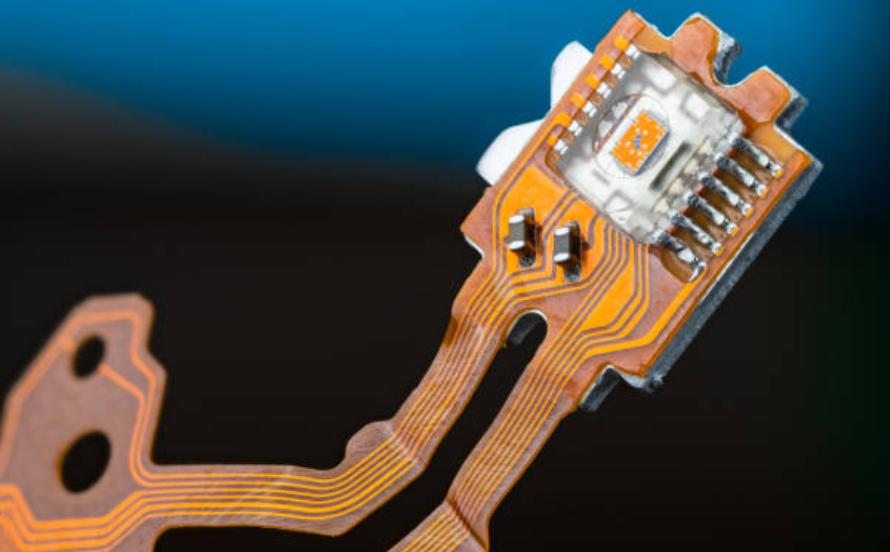
The connector at each end is where most of the cost and most of the risk sit. Automotive connectors are sealed, keyed and often have a lever or a slide to engage them, and the flexible circuit tail that enters the connector needs a stiffener to resist the insertion force. The stiffener thickness and the tail width are defined by the connector standard, so the cable layout has to be designed around it rather than the other way round.
Where the circuit is welded or soldered to a busbar rather than plugged into a connector, the joint has to survive the vehicle life. Ultrasonic welding is used for copper to copper joints because it does not melt the material, and the pad on the flex must have enough copper area to carry the weld energy without tearing. Terminations of this kind are usually qualified by a peel and a thermal cycle test on a coupon rather than by inspection of the production part.
Materials, Standards and Cost
The base material is polyimide because it tolerates the temperature range and the chemical exposure of a vehicle environment, and the copper is usually rolled annealed for fatigue resistance. Adhesive systems have to meet the same flammability and outgassing requirements as any other part in the cabin, and the finished cable is usually tested to the same vibration and thermal shock standards as a wire harness, which are published and well understood.
Cost is where the comparison becomes interesting. A flexible circuit has a higher tooling and design cost than a bundle of wires and a much lower assembly cost, because it arrives ready to fit with the connectors already attached. For a low volume vehicle the wire harness still wins, but as volume rises the crossover arrives quickly, and the repeatability of the finished part is an additional argument that does not appear in the piece price. The same reasoning about cable assembly applies to any product where the interconnect is a significant part of the build.
Additional Considerations for This Build
Practical attention to electric vehicle pays for itself here, because it decides whether the finished board behaves as the drawing intended. Where the requirement is not stated on the fabrication drawing or in the assembly notes, the shop has to assume a default, and that default is rarely the value the design was simulated with. Stating electric vehicle explicitly, together with the tolerance that applies, removes the assumption and keeps the result predictable from batch to batch.
Process Control and Verification
On a design of this kind, wire harness is the item that decides how the rest of the board is arranged. Where the requirement is not written down, the shop supplies its own default, and the default is chosen for the process rather than for the design. The measurements that matter are the repeatable ones: conductor width and spacing, annular ring, finished hole size, plating thickness and surface finish are all verifiable on a coupon that travels with the panel.
Related reading: our fabrication notes, board quality and design release notes cover the same ground.
FAQ
Can a flexible printed circuit carry high current? Yes, if the copper is thick enough and the conductor is wide. A flexible circuit for battery interconnection may use two or four ounce copper, and the current capacity is calculated exactly as it would be on a rigid board.
Is it repairable in the field? Usually the connector is, and the cable is not. A damaged flexible circuit is normally replaced as a unit, which is why protection against abrasion matters more than repairability in the design.
How is a flexible circuit fixed in place? With adhesive backed clips, with a bonded foam layer or with a push in retainer. The fixing method has to allow for the expansion of the cable over temperature and should not clamp it rigidly at a point where it bends.