FPC Connector Assembly on Commercial Printer Boards
A commercial printer control board connects to a display panel, sensors, a scanning assembly, motors and an operating keypad, and several flexible printed cable connectors are normally needed to do it. After assembly the joints can look perfectly acceptable, and then the cable refuses to lock, makes intermittent contact, or the connector body turns out to be slightly tilted. Insufficient solder is only one of the possible causes, and often it is not the cause at all.
What Decides a Connector Joint
The pad design of the connector, the aperture in the stencil, the support under the board, the placement position, the heat the part sees during reflow and the flatness of the component body all contribute to the result. A process that only confirms that the part has been soldered has ignored the assembly that follows, and the consequence appears at the point where the product is put together.
The two pad types are the reason a FPC connector is awkward. The signal pins are fine pitch and want a small amount of paste: too much produces a bridge, too little produces a joint that never forms properly. The mounting legs are large and carry the load when a cable is inserted and removed: a leg that is not fully soldered allows the body to move, and the movement damages the contact area above it.

Intake Data for the Connector
The Gerber data, the bill of materials, the placement coordinates, the assembly drawing, the panel information, the quantity and the lead time are requested as usual. For the connector, the full manufacturer part number is worth having, together with the direction of the contacts, the direction the cable is inserted, the orientation of the locking mechanism and the specification of the cable that will be used.
Connectors that look alike can differ in pin count, pitch, contact direction and overall height. Looking for a substitute on the basis that it has the same number of pins and the same footprint is not enough, because the substitute may not fit the cable or the shell. Where a substitute is permitted, the board pad, the mechanical dimensions and the assembly requirement are checked first and the customer confirms the replacement.
During import the reference designators, the packages and the orientations are checked across the bill of materials, the coordinates and the drawing. Where the angle in the coordinate file disagrees with the assembly drawing, the data are reconciled before the programme is written, because asking the operator to decide at the machine produces a different decision on a different shift.
Designing the Paste Deposit
Because the pads are not alike, the stencil aperture cannot treat them as one. The fine pins and the mounting legs are evaluated separately against their pad sizes, the structure of the part, the behaviour of the paste and the components nearby. After printing, the position and the continuity of the paste over the fine pins are examined specifically, not only the overall volume.
Support under the board matters more here than in most places. If the board is unsupported near the connector, the pressure of the squeegee can deflect it, and the result is a row of pins with the correct amount of paste and the next row with too little. That difference is a property of the fixture, and no amount of attention at the placement stage will correct it.
At placement, the nozzle and the pick position have some influence too. A long body picked off centre can rotate slightly as it travels or lands, and a placement force that is too high squeezes the paste out from under the pins and increases the chance of a bridge.
Inspecting the First Article
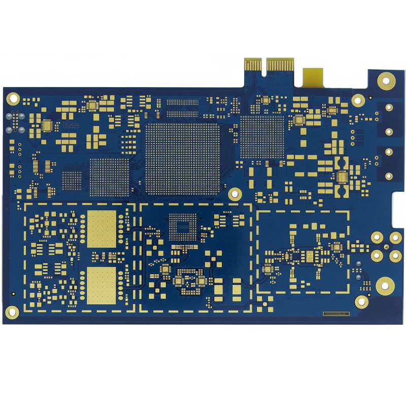
The vision system in the placement machine helps to confirm the outline and the position, but the first article is still checked physically: the orientation of the part, how flat the body sits, and how the pins line up with the pads. Where a resistor, a capacitor or a driver device sits close to the connector, the neighbours are checked as well, in case a machine correction moved one of them.
After reflow, optical inspection covers the offset, the bridging and the visible joints, and the fine pins and the mounting legs are examined again with the microscope, where wetting, bridges, the tilt of the body and the height difference between the legs can be seen directly. That last check is the one that connects the joint to the assembly, because a body that is not level does not lock a cable properly even when each joint is sound.
The Cable Trial Fit
A solder joint that measures correctly is not the same as an assembly that works. Where it is possible, the cable the customer specifies or a mechanical sample is inserted to check the action of the lock, the depth of insertion and the load the connector carries. An unmatched cable should not be used for repeated insertion, because the damage that results is a property of the test rather than of the product.
If contact becomes intermittent once the cable is in place, a known good board and the suspect board are compared, and the cable, the lock, the position of the connector body and the mounting legs are examined in turn. Without a fixed cable and fixed test conditions, a conclusion of poor soldering is not supported by anything.
Where programming and functional testing are included, the program revision, the interface definition, the supply conditions, the test steps and the acceptance criteria are needed. A printer board has many interfaces, so the scope of the order states which ports are actually tested.
Carrying Changes Forward
When a prototype leads to a change in the connector angle, in the placement coordinate or in the stencil aperture, the confirmed result belongs in the next revision of the production data rather than in an instruction given verbally to one shift. The same applies when the customer changes the connector model, because the mechanical dimensions and the cable have to be confirmed again.
Our SMT assembly lines place fine pitch connectors and inspect them, component procurement controls the connector part number and its source, and the programming, the functional test and the assembly follow under the records held by quality management.
What the Service Covers
`r`n
The work on this kind of board includes the placement of the connectors, the material, the programming, the functional test and the assembly that follows. Because the connector is both an electrical part and a mechanical part, the same group that places it also has an interest in the cable and the shell fitting afterwards, which is where a question about a contact direction or a lock orientation is answered from the drawing rather than from an assumption.
`r`n
Providing the whole flow in one place also means that the board revision and the connector part number are checked against the same data all the way through, so a change made at the prototype stage does not have to be rediscovered at the assembly stage of the next order.
FAQ
Why does a sound joint still give a bad cable fit? Because the joint and the mechanical seat are different requirements. A tilted body, a mounting leg that is not fully soldered or a connector that is not the specified part will all cause it.
Can a connector with the same pin count be substituted? Only after the pad, the mechanical dimensions and the cable have been confirmed and the customer has approved it.
Why is the cable test needed? It is the only check that covers the mechanical function the connector exists to perform.