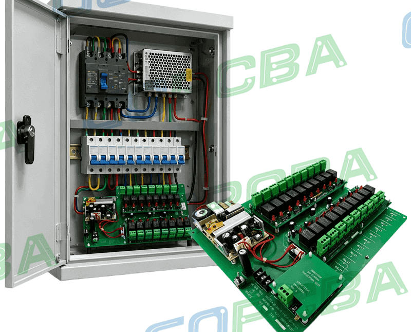
Fuse and Protection Selection on a Board
A fuse is a simple part that is frequently chosen badly. It has to pass the normal current without nuisance operation, interrupt the fault current without exploding, and coordinate with the rest of the protection.
The Two Ratings
The current rating is the current the fuse carries indefinitely without opening. It is specified at a particular ambient and it must be derated where the ambient is higher.
The breaking capacity is the maximum fault current the fuse can interrupt safely. Where the available fault current exceeds it, the fuse may arc and fail to clear the fault.
Both ratings matter, and a fuse selected only on the current rating can be a hazard. The available fault current is determined by the supply and the impedance of the circuit, and it is often much higher than the normal current.
Time Current Characteristics
The fuse does not open at its rated current; it opens after a time that depends on the current. The characteristic curve shows this relationship, and the shape determines the behaviour.
A fast acting fuse opens quickly at a modest overload, which is useful for protecting semiconductors. A slow blow fuse tolerates a short inrush current, which is necessary where the load is a motor or a capacitive input.
The characteristic is the reason a fuse that is correct in the steady state can operate at switch on, and why a fuse that tolerates the inrush can be too slow to protect the semiconductor. Our design release checklist notes where the coordination is recorded.
Coordination With the Load
The fuse must open before the protected device is damaged. The device’s surge rating defines the energy it can absorb, and the fuse’s characteristic must be fast enough at the fault current to stay inside it.
The comparison is made on the squared current time, which the device data sheet gives as a limit and the fuse curve gives as a function of current. The fuse’s value at the fault current must be less than the device’s limit.
Where the two are comparable, the coordination requires a faster fuse or a different device, and the choice should be made on the curves rather than on appearance. Our component selection notes describe the parameters used.

Ambient and Enclosure Effects
The rated current assumes an ambient and a mounting condition. Inside an enclosure the ambient is higher than outside and the fuse is surrounded by other heat sources, so it runs hotter and opens earlier.
The derating for temperature is given by the manufacturer as a curve, and applying it is the difference between a reliable design and one that opens on a warm day.
The fuse holder also matters. A clip with a poor contact adds resistance and heat, and a fuse in a holder runs hotter than one soldered directly. Where the fuse is soldered, the joint must be able to carry the fault current until the fuse operates.
Fuse Types
A cartridge fuse is the traditional type, available in many characteristics and breaking capacities. It requires a holder or a soldered connection.
A surface mount fuse is compact and suited to automated assembly. Its breaking capacity is usually lower than a cartridge fuse of the same size.
A resettable device opens on overcurrent and closes when the fault is removed. It is convenient and it does not provide the same protection, because it does not isolate the fault and its resistance is higher. Our quality notes describe the assembly checks for each type.
Verification
The verification is a fault current test at the maximum available fault current, confirming that the fuse opens and that nothing else is damaged.
The test should be performed on the final assembly configuration, because the enclosure and the trace impedance affect the result. A bench test with a bench supply may not produce the fault current the product can deliver.
The normal operation test at the maximum ambient confirms that the fuse does not operate spuriously, and both tests together define the acceptable window.
Design Checklist
Determine the normal current, the inrush and the available fault current. Choose a characteristic that tolerates the inrush and coordinates with the protected device, and a breaking capacity above the fault current.
Derate the current rating for the in-enclosure ambient. Check the holder and the soldered joint for the fault current.
Mark the rating on the board or in the documentation, since a replacement of the wrong rating defeats the design. Where the fuse is accessible to the user, the marking must be durable and unambiguous.
Process Control and Verification
On a design of this kind, coordination is the item that decides how the rest of the board is arranged. Keeping a sample from the panel turns a dispute into a measurement, because the same coupon can be re-examined by both parties without rebuilding the batch. Reviewing the design before the data is released is cheaper than correcting it after the panel is in the tank, because every step downstream inherits the decision made at the front end.
Documenting the assumption is part of the design work, and a short note on the drawing prevents a question that would otherwise arrive a day later and cost a day of schedule. The process window is set by the narrowest step in the flow, so an improvement anywhere else shows up as margin rather than as yield until that step is addressed.
A short note on the drawing about handling, storage or packaging is often worth more than an extra decimal place on a tolerance.
Process Control and Verification
On a design of this kind, coordination is the item that decides how the rest of the board is arranged. Keeping a sample from the panel turns a dispute into a measurement, because the same coupon can be re-examined by both parties without rebuilding the batch. Reviewing the design before the data is released is cheaper than correcting it after the panel is in the tank, because every step downstream inherits the decision made at the front end.
Documenting the assumption is part of the design work, and a short note on the drawing prevents a question that would otherwise arrive a day later and cost a day of schedule.
Process Control and Verification
On a design of this kind, coordination is the item that decides how the rest of the board is arranged. Keeping a sample from the panel turns a dispute into a measurement, because the same coupon can be re-examined by both parties without rebuilding the batch. Reviewing the design before the data is released is cheaper than correcting it after the panel is in the tank, because every step downstream inherits the decision made at the front end.
FAQ
Can a fuse be replaced by a resistor? No. A resistor does not interrupt the fault and it dissipates the fault energy continuously, which is a fire risk.
Is a higher rated fuse safer? No. It delays the interruption and may allow the protected device to be damaged before the fuse operates.
What does gopcb provide for protection design? We provide normal, inrush and fault current analysis, fuse selection with the characteristic and breaking capacity, coordination against the device surge rating, in-enclosure derating, and fault current testing on the production configuration.