High Frequency PCB Routing: Fewer Vias, Shorter Paths, Less Coupling
High frequency PCB routing follows from a small number of physical facts. A trace radiates in proportion to its length, a via adds capacitance and a discontinuity, a corner reflects, and two parallel traces exchange energy. Every rule below is a consequence of one of those, and each of them is applied at the layout stage, where the cost of compliance is time rather than board area.
Use Enough Layers
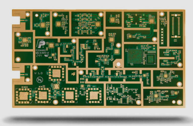
Dense high frequency circuitry generally needs a multilayer board, not because the interconnections cannot fit on two layers, but because the inner layers provide the reference planes that every fast trace needs. An inner layer can also be used as a shield between routing layers, and the short distance from a signal to its reference plane reduces the loop area, the parasitic inductance and the coupling to neighbouring traces.
As a rough comparison, a four layer board with solid planes is far quieter than a two layer board of the same size and material. The trade is cost and process complexity, which is why the layer assignment is a design decision taken with the routing density rather than before it, and it is constrained by the fabrication capability.
Minimise the Via Count
Every via in a signal path adds a small capacitance and breaks the impedance of the trace. In a high speed interface, a net that changes layer four times has four discontinuities and four opportunities for a reflection, and the transmitted signal degrades accordingly. Reducing via count is therefore one of the most direct improvements available.
Where a layer change is unavoidable, place a ground via adjacent to it so that the return current can follow, and avoid using two vias where one would serve. The same reasoning explains why a package that requires a via per ball is a layout constraint rather than a layout choice: the escape pattern is fixed by the package, and the designer controls only the routing beyond it.

Keep the Trace Short
The radiated field, the coupled noise and the loss all grow with trace length, so the shortest route between two points is generally also the electrically best one. This is why placement matters more than routing in a high frequency design, and why the placement review comes first: if the clock source, the memory and the interface connectors are placed where the connections between them are short, the routing has less to compensate for.
Trace length also determines whether the trace behaves as a transmission line at all. When the propagation delay is small compared with the edge rise time, the trace looks electrically short and its impedance does not matter much; as the ratio grows, the trace becomes a transmission line and everything that follows from that applies. Shortening the trace is one way to keep it in the benign regime.
Corners and Continuity
A right angle corner is a small impedance discontinuity and, at high frequency, a place where the field concentrates. Forty five degree bends or arcs preserve the geometry of the trace better and are the standard practice; at lower frequencies the same rule is usually applied for a different reason, which is the mechanical adhesion of the copper.
Continuity of width matters as much as the angle. A trace that narrows to pass between two pads and then widens again has two discontinuities, and it also has a section of higher impedance. Where the narrowing is unavoidable, the length of the narrow section should be as short as possible.
<img src="https://www.gopcba.com/wp-content/uploads/2026/09/49-2.jpg" alt="ground shielding around a clock trace” />
Crosstalk and Shielding
Crosstalk is the coupling of energy from one trace into another through the electric and magnetic fields they share. Its magnitude depends on the spacing, the length over which the traces run parallel, the edge rate of the aggressor, the impedance of the victim and the way the traces are terminated.
The available countermeasures are geometric. Increase the separation between the traces, and place a grounded trace or a ground pour between them where the layout allows. Reduce the parallel length, and route a clock perpendicular to a sensitive signal rather than alongside it. Where long parallel runs cannot be avoided on one layer, route the adjacent layer orthogonally so that the broadside coupling does not accumulate along the same distance.
Ground shielding is applied specifically to the most aggressive nets. A clock trace enclosed by ground copper, with ground vias placed along the shield at intervals, confines its field and protects the neighbours; the enclosure is only effective if the via pattern is complete, because a shield with gaps behaves as a slot. Differential clocks, routed as a pair with their own reference, achieve a similar result with a lower common mode component.
Unused Inputs and Ground Handling
An unconnected input is not neutral. A floating gate or input can sit at an indeterminate level, can oscillate, and behaves as a small antenna that couples noise into the rest of the circuit. Terminating unused inputs to ground or to the supply removes the problem, and in high frequency terms the supply is also a ground through the decoupling network.
The grounds themselves need care. Digital and analogue return currents should not share a path, and where the two references meet it should be at a defined point or through a component chosen for the purpose. What must be avoided is a fast digital return current flowing through the reference used by an analogue circuit, because the resulting voltage appears directly in the analogue signal, which is the failure mode the final test should be able to detect.
Applying the Rules
The sequence that works is to plan the layer assignment and the reference planes first, then place the components so that the critical connections are short, then route the fastest and most sensitive nets first while the board is still empty. Check the via count, the trace length and the parallel runs on those nets before moving to the slower signals, because the space to fix them is only available early. The copper weight and dielectric thickness behind those planes are a manufacturing decision that should be fixed at the same time.
The final check is a measurement rather than a rule: on the assembled board, confirm the signal quality at the receiver and the disturbance on the supply while the interface runs at its highest rate. That measurement is what converts a set of layout conventions into an understanding of where the margin actually lies.
FAQ
Is a four layer board always better than two? For high frequency circuitry, generally yes, because the planes it provides are the reference the signals need. For a slow design, the extra layers may add cost with no benefit.
How much does one via matter? Its capacitance is small, but its effect grows with the data rate. On a multi gigabit link, the difference between one via and three is measurable.
Does the 45 degree rule matter at low frequency? Electrically, very little. It is still applied because it is harmless and because the same routing practice is used throughout the design.
What single change reduces crosstalk most? Reducing the length over which two aggressive nets run in parallel, followed by increasing the spacing between them.
Summary
High frequency PCB routing is a discipline of reducing what the geometry adds: fewer vias, shorter traces, smoother corners, more spacing between aggressive nets, an intact ground shield around the clocks, and grounds that keep noisy return currents away from sensitive references. Each rule is a consequence of the physics rather than a convention, and each is cheapest to apply while the layout is still being planned.