How to Choose PCB Components: PCB Design, PCB Manufacturing & Component Selection Guide
The development and implementation of a printed circuit board (PCB) is a complex process, and one of the most important stages is selecting the right electronic components. In PCB Design, component selection affects far more than the electrical function of a circuit. It can also influence performance, reliability, cost, thermal behavior, assembly efficiency, and even the manufacturability of the final product.
Choosing appropriate PCB Components at the beginning of a project can simplify PCB assembly, reduce production risks, improve product reliability, and extend the service life of electronic equipment. On the other hand, selecting components without considering electrical, mechanical, thermal, or supply-chain requirements can create problems later in the design and PCB Manufacturing process.
This guide explains how to select suitable components for a PCB, including resistors, capacitors, diodes, transistors, integrated circuits, and connectors. It also covers component sourcing, compatibility, reliability, lifecycle management, and manufacturing considerations.
What Are PCB Components?
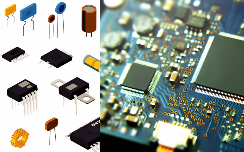
PCB Components are electronic devices mounted on a printed circuit board to create functional electrical circuits. Depending on the application, a PCB may contain passive components, active semiconductor devices, electromechanical components, connectors, sensors, and other specialized devices.
Common PCB components include:
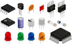
- Resistors
- Capacitors
- Diodes
- Transistors
- Integrated circuits (ICs)
- Inductors
- Connectors
- Crystals and oscillators
- Relays
- Switches
- Sensors
- Fuses and protection devices
These components are attached to the PCB using technologies such as through-hole assembly (THT) or surface-mount technology (SMT).
The selected components work together with copper traces, vias, power planes, and other PCB structures to perform the intended electrical functions. Therefore, component selection should always be considered together with PCB layout and manufacturing requirements.
PCB Requirements You Should Define Before Selecting Components
The first step in component selection is to clearly define what the PCB must accomplish.
A component should not be selected simply because it has the required nominal electrical value. Engineers should also consider operating conditions, tolerances, availability, package dimensions, thermal performance, reliability, and manufacturing compatibility.
1. Functional Requirements
Define the exact function of the PCB and its major circuit blocks.
For example, the board may need to perform:
- Power conversion
- Signal amplification
- Digital processing
- Data communication
- Motor control
- Sensor measurement
- Battery management
- Wireless communication
- Audio processing
Understanding the circuit function narrows down the types of components that can be used.
2. Power Requirements
Determine the expected:
- Input voltage
- Output voltage
- Operating current
- Peak current
- Power consumption
- Startup current
- Power dissipation
Component voltage and current ratings should provide adequate margin for normal operation and expected transients.
Thermal design is equally important. A component may meet its electrical rating but still exceed its allowable junction or case temperature if heat cannot be removed effectively.
3. Environmental Conditions
The operating environment can strongly influence component selection.
Consider whether the PCB will operate under:
- High or low temperatures
- High humidity
- Vibration
- Mechanical shock
- Dust
- Corrosive environments
- Outdoor exposure
- Automotive conditions
- Industrial environments
For demanding applications, engineers may need components with extended temperature ratings, improved mechanical robustness, or specific environmental qualifications.
4. Size and Weight Constraints
Portable and compact electronic products often require small PCB components.
Package size affects:
- PCB area
- Component density
- Routing space
- Thermal performance
- Assembly capability
- Inspection requirements
Smaller components can save board space, but extremely small packages may increase assembly and inspection challenges.
5. Cost Targets
Component selection directly affects the total PCB Assembly cost.
Engineers should evaluate not only the unit price but also:
- Assembly cost
- Availability
- Minimum order quantity
- Lead time
- Tooling requirements
- Inspection requirements
- Expected failure rate
- Replacement cost
The lowest-cost component is not necessarily the lowest-cost solution over the entire product lifecycle.
Researching and Sourcing PCB Components
Once the technical requirements are defined, the next step is to research and source suitable components.
Reliable distributors and authorized supply channels can provide datasheets, lifecycle information, pricing, stock information, and technical documentation.
Engineers should avoid selecting components based only on availability at the time of prototype development.
Component Lifecycle
Component lifecycle status is an important consideration for products expected to remain in production for many years.
Common lifecycle stages include:
- Active
- New product introduction
- Not recommended for new designs
- End of life
- Obsolete
For long-life industrial, automotive, medical, or infrastructure products, component lifecycle planning can be particularly important.
A component that is readily available today may become difficult to source several years later.
Cost vs. Quality
Cost reduction is important, but excessive cost reduction can increase long-term risks.
A lower-priced component may have different:
- Tolerance
- Temperature characteristics
- Reliability
- Electrical performance
- Manufacturing consistency
- Availability
A proper component-selection strategy evaluates total cost of ownership rather than focusing exclusively on purchase price.
Key PCB Components and Selection Criteria
The following are some of the most common components used in electronic circuit design.
1. Resistors
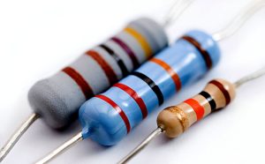
Resistors are fundamental passive components used to control current, establish voltage relationships, provide biasing, terminate signals, and dissipate electrical energy.
When selecting resistors, consider the following parameters.
Resistance Value
The resistance value must match the electrical requirements of the circuit.
For precision applications, the nominal resistance and tolerance should be selected according to the required accuracy.
Tolerance
Tolerance determines how much the actual resistance may differ from its nominal value.
Common tolerances include:
- ±10%
- ±5%
- ±1%
- ±0.5%
- ±0.1%
Precision analog circuits and measurement systems may require tighter tolerances than general-purpose circuits.
Power Rating
The resistor’s power rating must be sufficient for the expected power dissipation.
A resistor that continuously operates close to or above its rated power can overheat and eventually fail.
Engineers should consider both steady-state power and transient conditions.
Temperature Coefficient
The temperature coefficient of resistance (TCR) indicates how resistance changes with temperature.
Low-TCR resistors are useful in precision applications where resistance stability is important.
Resistor Technology
Common resistor technologies include:
- Thick-film
- Thin-film
- Metal-film
- Wirewound
The appropriate technology depends on resistance accuracy, power handling, noise, frequency behavior, cost, and application requirements.
2. Capacitors
Capacitors are among the most widely used PCB Components. They are used for decoupling, filtering, energy storage, timing, coupling, noise suppression, and power-supply stabilization.
Capacitance
The capacitance value should satisfy the requirements of the circuit.
However, the nominal capacitance printed on a component may change with voltage, temperature, frequency, and aging depending on the capacitor technology.
Rated Voltage
The capacitor’s rated voltage must be greater than the maximum voltage it will experience under normal operation and foreseeable transient conditions.
Rather than applying a universal 1.5× rule, engineers should select an appropriate voltage margin based on the capacitor technology, application requirements, transients, reliability target, and manufacturer recommendations.
Temperature Characteristics
Temperature can significantly affect capacitance and other capacitor characteristics.
For ceramic capacitors, dielectric selection is especially important.
For example, Class 1 ceramic dielectrics such as C0G/NP0 provide excellent stability, while Class 2 dielectrics such as X5R and X7R provide higher capacitance density but have voltage and temperature dependencies that must be considered.
Capacitor Type
Common capacitor types include:
- Ceramic capacitors
- Aluminum electrolytic capacitors
- Tantalum capacitors
- Film capacitors
The appropriate type depends on capacitance, voltage, ESR, ripple current, frequency, physical size, lifetime, and application requirements.
3. Diodes
Diodes are semiconductor devices used for rectification, protection, switching, voltage regulation, clamping, and signal processing.
Important selection criteria include:
Forward Voltage
Forward voltage affects power dissipation and efficiency.
Low-forward-voltage devices such as Schottky diodes can be advantageous in certain low-voltage or high-frequency applications.
Reverse Voltage
The diode must be capable of withstanding the maximum expected reverse voltage, including appropriate transient margin.
Exceeding the reverse-voltage rating can cause breakdown and permanent damage.
Forward Current
The diode’s continuous and peak current ratings should accommodate the expected circuit current.
Thermal conditions must also be considered because forward current produces power dissipation.
Switching Speed
For high-frequency circuits, reverse-recovery characteristics can significantly affect performance.
Fast-recovery and Schottky diodes may be appropriate for certain switching applications.
Diode Type
Different diode types serve different purposes:
- Rectifier diodes for power conversion
- Schottky diodes for low-forward-voltage applications
- Zener diodes for voltage regulation and protection
- TVS diodes for transient protection
- LEDs for optical indication or illumination
- Photodiodes for light detection
4. Transistors
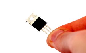
Transistors are widely used for switching, amplification, regulation, and signal processing.
Two common transistor families are bipolar junction transistors (BJTs) and metal-oxide-semiconductor field-effect transistors (MOSFETs).
Transistor Type
The required circuit function determines the transistor technology.
BJTs can be useful for analog amplification and certain switching applications, while MOSFETs are widely used for efficient switching and power management.
Voltage and Current Ratings
The transistor must tolerate the expected voltage and current, including relevant transient conditions.
For MOSFETs, important parameters may include:
- Drain-source voltage
- Continuous drain current
- RDS(on)
- Gate threshold voltage
- Gate charge
For BJTs, engineers may consider:
- Collector-emitter voltage
- Collector current
- DC current gain
- Saturation voltage
Switching Performance
High-speed switching applications require careful evaluation of switching losses, gate charge, capacitances, and thermal behavior.
A MOSFET with low conduction resistance may still produce significant switching losses at high frequency if its switching characteristics are unsuitable.
Thermal Management
Power transistors can generate substantial heat.
Depending on the power level, thermal management may require:
- Copper areas
- Thermal vias
- Heat sinks
- Metal-core PCBs
- Forced-air cooling
Therefore, component selection and PCB thermal design should be evaluated together.
5. Integrated Circuits (ICs)
Integrated circuits are often the functional core of modern PCBs because they can integrate complex electronic functions into a single device.
Examples include:
- Microcontrollers
- Microprocessors
- Memory devices
- Power-management ICs
- ADCs and DACs
- Motor drivers
- Communication ICs
- Audio ICs
- Sensor interfaces
Function
Select an IC that provides the required functionality and meets the system architecture.
Engineers should review the complete datasheet rather than selecting a device based only on its headline specifications.
Operating Voltage
Verify:
- Supply-voltage range
- Input-voltage range
- Output-voltage requirements
- Logic thresholds
- Maximum absolute ratings
Voltage compatibility is essential when multiple ICs operate from different power domains.
Package Type
The IC package directly affects PCB Design and assembly.
Common packages include:
- DIP
- SOIC
- QFP
- QFN
- DFN
- BGA
- CSP
Package selection should consider PCB footprint, routing density, thermal performance, inspection method, assembly capability, and manufacturing yield.
Availability and Lead Time
Supply-chain conditions should be considered early in the design process.
For production products, engineers should evaluate:
- Authorized sourcing
- Current inventory
- Lead time
- Lifecycle status
- Second-source options
- Approved alternatives
This can help prevent production delays caused by component shortages.
6. Connectors
Connectors provide electrical and mechanical interfaces between the PCB and external devices, cables, power sources, or other circuit boards.
Connector Type
The connector must match the intended interface and application.
Examples include:
- USB
- HDMI
- Ethernet
- Board-to-board connectors
- Wire-to-board connectors
- Pin headers
- FFC/FPC connectors
- Coaxial connectors
Number of Contacts
The number of pins or contacts must match the required electrical connections.
Signal assignment, power contacts, grounding, and unused pins should all be considered during connector selection.
Durability
If the connector will be repeatedly plugged and unplugged, its rated mating-cycle count becomes an important parameter.
Contact material, plating, retention force, and mechanical construction also affect long-term reliability.
Size
Compact connectors can help reduce PCB area, but smaller connectors may require tighter PCB tolerances and more precise assembly.
Component Compatibility and Interoperability
Selecting individual components is only part of the process. Components must also operate correctly together.
This is particularly important when a PCB combines high-speed digital circuits, sensitive analog circuits, power electronics, RF circuits, and communication interfaces.
EMI and Signal Compatibility
Electromagnetic interference (EMI) can affect sensitive circuits.
Engineers should consider:
- Component placement
- Grounding
- Return paths
- Filtering
- Shielding
- Trace routing
- Differential-pair routing
- Switching-node isolation
Noise-generating components such as switching regulators should be physically and electrically managed to minimize interference with sensitive analog or RF circuits.
Thermal Compatibility
Heat generated by one component can affect nearby components.
High-power devices should be evaluated for:
- Power dissipation
- Junction temperature
- Thermal resistance
- Copper area
- Thermal vias
- Heat sinks
- Airflow
Thermal simulation or measurement may be appropriate for high-power designs.
Power Compatibility
All components connected to a power rail must be compatible with its voltage and current capabilities.
Engineers should calculate:
- Continuous current
- Peak current
- Startup current
- Power dissipation
- Regulator capacity
- Voltage tolerance
Appropriate power margins help improve system stability and reliability.
Component Footprints and PCB Manufacturing Compatibility
One important aspect of component selection is the relationship between the component package and the PCB footprint.
An electrically suitable component may still create manufacturing problems if its package is difficult to assemble or inspect.
During PCB Manufacturing, engineers should verify:
- Correct land pattern
- Pad dimensions
- Solder-mask openings
- Component courtyard
- Pick-and-place requirements
- Component orientation
- Assembly clearances
- Reflow compatibility
- Inspection accessibility
For BGA, QFN, CSP, and other fine-pitch packages, footprint accuracy is particularly important.
Incorrect footprints can cause soldering defects, insufficient clearances, assembly yield problems, or expensive PCB redesigns.
Quality and Reliability Testing
Testing is an essential part of the component-selection process, especially for products used in demanding or safety-critical applications.
Component-Level Testing
Depending on the application, reliability evaluation may include:
- Thermal cycling
- High-temperature operating tests
- Humidity testing
- Vibration testing
- Mechanical shock
- Burn-in
- Electrical stress testing
Not every component requires every test. The appropriate qualification plan depends on the product, application, component technology, and applicable standards.
Compliance Standards
Components and assemblies may need to comply with relevant requirements such as:
- RoHS
- REACH
- IPC standards
- UL requirements
- Automotive qualification requirements
- Industry-specific regulations
Compliance requirements should be defined early because they can affect both component selection and manufacturing.
Manufacturer Reliability
A reliable component supplier should be able to provide appropriate technical documentation, which may include:
- Datasheets
- Application notes
- Reliability reports
- Qualification information
- Material declarations
- Lifecycle information
- PCN/EOL notifications
This documentation supports engineering validation and long-term product management.
A Practical PCB Component Selection Checklist
Before finalizing the BOM, engineers can use the following checklist:
| Selection Factor | Key Questions |
|---|---|
| Electrical performance | Does the component meet voltage, current, frequency, and tolerance requirements? |
| Package | Is the package compatible with the PCB layout and assembly process? |
| Thermal performance | Can the component operate within its temperature limits? |
| Reliability | Is the component suitable for the intended operating environment? |
| Lifecycle | Will the component remain available throughout the product lifecycle? |
| Supply chain | Is it available from reliable and authorized sources? |
| Cost | Does it meet the target cost without compromising requirements? |
| Compliance | Does it meet applicable regulatory and industry requirements? |
| Manufacturability | Can it be assembled, inspected, and tested reliably? |
| Alternatives | Is there an approved second source or replacement option? |
Best Practices for PCB Component Selection
A structured component-selection process can reduce both engineering and manufacturing risks.
Define Requirements Before Choosing Parts
Do not begin with a favorite component and then design the circuit around it without evaluating alternatives.
Start with electrical, mechanical, environmental, cost, and manufacturing requirements.
Review the Complete Datasheet
Important parameters are often found outside the headline specifications.
Engineers should review:
- Absolute maximum ratings
- Recommended operating conditions
- Electrical characteristics
- Thermal characteristics
- Package information
- Application circuits
- Derating requirements
Consider the Entire Product Lifecycle
Prototype availability does not guarantee long-term production availability.
Lifecycle planning is particularly important for products expected to remain in production for many years.
Design for Manufacturing
Component selection should be coordinated with the PCB fabricator and assembly provider when appropriate.
A component may be technically suitable but difficult to manufacture at the required production volume.
Maintain an Approved BOM
Document approved component manufacturers, part numbers, alternates, revisions, and qualification status.
This reduces the risk of uncontrolled substitutions during production.
Validate Critical Components
For critical components, prototype testing and engineering validation should be completed before mass production.
Electrical performance, thermal behavior, mechanical reliability, and environmental performance should be evaluated according to the application’s requirements.
How Component Selection Affects PCB Design and Manufacturing
Component selection has a direct relationship with the complete PCB development process.
A large BGA may require more PCB layers and tighter routing rules. A high-current MOSFET may require larger copper areas and thermal vias. A high-speed connector may require controlled impedance and carefully designed return paths.
Therefore, component selection can influence:
- PCB layer count
- Board dimensions
- Routing density
- Trace width
- Impedance control
- Thermal design
- Manufacturing tolerances
- Assembly process
- Inspection methods
- Final product cost
This is why PCB Design and PCB Manufacturing should not be treated as completely separate stages.
Early collaboration between design engineers, component suppliers, PCB manufacturers, and assembly providers can identify potential problems before they become expensive redesigns.
Kingda PCB Manufacturing and Assembly Support
Kingda provides PCB manufacturing and assembly solutions for customers requiring reliable and production-ready circuit boards.
From component selection and DFM evaluation to PCB fabrication, assembly, inspection, and testing, a coordinated manufacturing process can help reduce production risks and improve product consistency.
For complex projects, engineers can evaluate component packages, PCB stackup, thermal requirements, assembly capabilities, and testing requirements together before production begins.
This approach helps ensure that the selected components are not only electrically suitable but also compatible with the complete PCB Manufacturing process.
Conclusion
Selecting the right components for a PCB assembly requires much more than finding components with the correct nominal values. Engineers must consider electrical performance, package type, thermal behavior, reliability, environmental conditions, lifecycle status, supply-chain availability, compliance, and manufacturing compatibility.
Resistors, capacitors, diodes, transistors, ICs, and connectors each have different selection criteria. At the same time, components must work together as a complete system without creating unnecessary EMI, thermal, power, or mechanical problems.
A successful component-selection strategy begins with clearly defined design requirements and continues through datasheet analysis, sourcing, prototype validation, reliability testing, and production qualification.
By integrating component selection with PCB Design, PCB Assembly, and PCB Manufacturing, engineers can reduce redesigns, improve manufacturing yield, control costs, and build more reliable electronic products.
SEO Keywords
PCB Components, PCB Design, PCB Manufacturing, PCB Assembly, PCB Component Selection, Electronic Components, PCB Parts, PCB Design Guidelines, Component Selection, PCB Manufacturing Process
Google TDK
Title:
How to Choose PCB Components: PCB Design, PCB Manufacturing & Selection Guide
Description:
Learn how to choose PCB components based on electrical performance, package type, thermal requirements, reliability, lifecycle, cost, compatibility, and PCB manufacturing requirements.
Keywords:
PCB Components, PCB Design, PCB Manufacturing, PCB Assembly, PCB Component Selection, Electronic Components, PCB Parts, PCB Design Guidelines, Component Selection, PCB Manufacturing Process