How to Desolder PCB Components: PCB Manufacturing, PCB Assembly & Repair Guide
Printed circuit boards (PCBs) have become indispensable components in almost every modern electronic product and consumer device. From the initial design stage to the finished product, manufacturing a complete PCB assembly involves multiple processes. A typical PCB consists of a substrate and numerous electronic components mounted on its surface or through its drilled holes. These components are permanently attached to the board through soldering.
Soldering is essential for establishing reliable mechanical and electrical connections between electronic components and the PCB. When the appropriate materials, processes, and assembly methods are used, the finished board can meet the required electrical and mechanical specifications.
However, electronic components can fail during manufacturing, testing, operation, or long-term use. In some cases, the root cause of a malfunction is simply a damaged or defective component. If the faulty component can be safely removed and replaced with a functional one, the PCB may be restored without manufacturing an entirely new board.
The process of removing soldered components from a PCB is called desoldering.
This article explains how to desolder PCB components, introduces several common desoldering techniques, and discusses important precautions for PCB repair, rework, and component replacement.
Why Is Desoldering Necessary?
As electronic products become smaller and more sophisticated, PCB Assembly has become increasingly dense and complex. Components are packed into smaller areas, while multilayer boards and fine-pitch packages are increasingly common.
When a PCB develops a problem, replacing the entire board is not always necessary. In many cases, only one or a few components may be defective. Proper desoldering allows technicians to remove these components and replace them with functioning parts.
There are several reasons why desoldering is important:
- PCB repair: Removing a failed component can restore the functionality of an otherwise usable circuit board.
- Component replacement: Components with incorrect specifications, manufacturing defects, or damage can be removed and replaced.
- Prototype modification: Engineers can remove and replace components while testing different circuit configurations.
- Rework: Manufacturing defects identified during inspection may require component removal and replacement.
- Cost reduction: Repairing a defective PCB can be more economical than manufacturing a completely new board.
- Sustainability: Repairing and reusing electronic assemblies can help reduce material waste and extend product life.
Proper desoldering is therefore an important skill in PCB Manufacturing, PCB assembly, electronics repair, and product rework.
Common PCB Desoldering Techniques
Before selecting a desoldering method, first identify the component type, package, soldering technology, PCB structure, and sensitivity of the surrounding components.
Always disconnect the power supply before beginning work. The PCB should also be handled using appropriate electrostatic discharge (ESD) precautions to minimize the risk of damaging sensitive electronic components.
Different components and PCB assemblies require different techniques.
1. Using a Desoldering Pump
A desoldering pump, also known as a solder sucker, is particularly useful for removing through-hole components.
First, use a soldering iron to heat the solder joint. Once the solder has completely melted, position the nozzle of the desoldering pump close to the molten solder.
Press the release mechanism to create suction and remove the molten solder from the joint.
Repeat the process as necessary until sufficient solder has been removed and the component leads can be released.
This technique works particularly well for relatively large through-hole solder joints. However, timing and coordination are important because solder can cool quickly after the heat source is removed.
When the solder is fully molten and the pump is positioned correctly, the solder can be removed efficiently without excessive mechanical force.
2. Using a Soldering Iron
Using a conventional soldering iron is one of the simplest and most widely accessible desoldering methods.
Apply a small amount of flux to the solder joint and heat the soldering iron to an appropriate temperature. Place the tip directly on the solder joint until the solder becomes completely molten.
The component lead can then be gently released from the PCB.
For stubborn joints, adding a small amount of fresh solder can improve heat transfer and help the existing solder melt more effectively.
This method is inexpensive and practical for many through-hole and accessible surface-mount components. However, excessive heat or prolonged contact with the PCB can damage copper pads, traces, or nearby components.
Extra care is required when working with multilayer PCBs, fine-pitch components, or boards with thermally demanding copper structures.
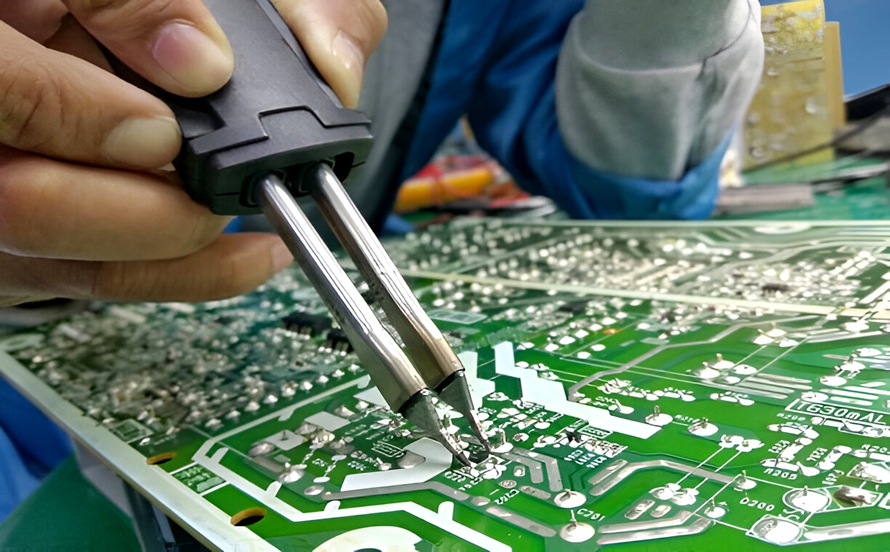
3. Using a Desoldering Gun
A desoldering gun combines heating and solder removal into a single tool. It is particularly useful when frequent component removal is required.
Before use, allow the desoldering gun to reach its specified operating temperature. Position the heated tip over the solder joint and activate the vacuum mechanism.
The molten solder is then drawn into the tool.
After removing the solder, inspect the joint and repeat the process if necessary. The component can then be removed once its leads are sufficiently free of solder.
Desoldering guns are generally more expensive than basic soldering irons and require regular cleaning and maintenance. However, they can significantly improve efficiency for technicians who perform repeated PCB Repair or rework operations.
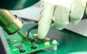
4. Using a Hot-Air Rework Station
Surface-mount devices (SMDs), particularly ICs and components with many closely spaced pins, can be more difficult to remove using a conventional soldering iron.
A hot-air rework station is often a more appropriate solution for these components.
A typical process includes:
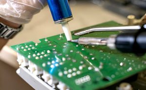
- Secure the PCB on a stable work surface.
- Apply an appropriate amount of flux around the component.
- Set the hot-air temperature and airflow according to the component, solder alloy, and PCB requirements.
- Preheat the surrounding PCB area when appropriate.
- Move the hot-air nozzle evenly around the component.
- Wait until the solder joints are completely molten.
- Gently lift the component using suitable tweezers or a vacuum pickup tool.
- Allow the PCB to cool before further processing.
Because the heat is distributed over the component rather than concentrated on individual pins, hot-air rework can be particularly useful for removing fine-pitch SMDs.
However, excessive temperature or airflow can damage nearby components, solder mask, PCB materials, or the component itself. Temperature and heating time should therefore be carefully controlled.
What to Do After Desoldering
Desoldering is generally considered a rework or repair operation rather than a standard PCB fabrication step.
After removing a component, the PCB should be carefully inspected and prepared for the replacement component.
First, remove residual solder and flux from the affected area. Excess solder can interfere with the replacement component or create unintended electrical connections.
The desoldered area should then be inspected for:
- Lifted solder pads
- Damaged copper traces
- Cracked solder mask
- Excessive solder residue
- Damaged vias
- Burn marks or thermal damage
- Mechanical damage around the component footprint
If a copper pad or trace has been damaged, additional PCB Repair may be required before installing the replacement component.
After the repair area has been cleaned and inspected, the replacement component can be installed according to the original schematic, PCB layout, and assembly specifications.
Depending on the application, the repaired PCB should then undergo visual inspection and electrical or functional testing.
Common Mistakes to Avoid When Desoldering PCB Components
Desoldering requires careful control of temperature, time, force, and tool selection. Poor technique can cause more damage than the original component failure.
The following mistakes should be avoided.
Avoid Excessive Heat
Excessive temperature or prolonged heating can damage:
- PCB solder pads
- Copper traces
- Solder mask
- Component bodies
- Nearby components
- PCB laminate materials
Use the lowest practical temperature that allows the solder to melt effectively, and avoid keeping the heating tool on the PCB longer than necessary.
Do Not Force a Component Out
Always make sure the solder is completely molten before attempting to remove a component.
Pulling or twisting a component while solder remains solid or partially molten can lift copper pads, damage plated-through holes, or tear traces from the PCB.
This is particularly important for through-hole components because their leads may be mechanically anchored to plated holes.
Remove Excess Solder After Desoldering
Residual solder should be removed from the component footprint before installing the replacement part.
A solder wick or desoldering tool can be used to remove excess solder and prepare the pads for the next assembly operation.
A clean and properly prepared footprint makes subsequent soldering easier and reduces the risk of solder bridges.
Use Flux Appropriately
Flux helps improve solder wetting and heat transfer by removing oxides from the soldering surfaces.
Using an appropriate amount of flux can make solder removal easier and reduce the amount of heat and mechanical force required.
However, flux residues should be cleaned when required by the PCB assembly process or component manufacturer’s recommendations.
Protect Nearby Components
When using hot air, the surrounding components should be protected from unnecessary heat exposure.
Sensitive components may require shielding or localized heating techniques. The airflow should also be controlled to prevent small components from being displaced.
Desoldering in PCB Repair and Rework
Desoldering is an important part of the broader PCB Assembly and repair workflow.
In production environments, defective assemblies may be identified through inspection or electrical testing. Depending on the nature of the defect, technicians may remove a defective component, clean the footprint, install a replacement, and then repeat the appropriate inspection or functional test.
For prototype development, desoldering is also useful because engineers can modify component values, replace integrated circuits, test alternative components, or correct assembly mistakes without discarding the entire PCB.
As PCB designs become more compact and component density increases, proper rework techniques become increasingly important. Fine-pitch packages, multilayer PCBs, microvias, and densely routed traces leave less room for error.
Technicians therefore need to understand the relationship between component package design, soldering technology, PCB construction, thermal characteristics, and rework methods.
Conclusion
Learning how to desolder PCB components is an essential skill for PCB repair, rework, prototyping, and component replacement. Whether using a desoldering pump, soldering iron, desoldering gun, or hot-air rework station, the objective is the same: remove the defective component without damaging the PCB or surrounding components.
The key to successful desoldering is controlling heat, minimizing mechanical force, selecting the appropriate tool, and carefully inspecting the PCB after component removal.
For high-density and multilayer PCBs, the process requires even greater precision because excessive heat or mechanical force can damage pads, traces, vias, and nearby components.
At Kingda, careful manufacturing, assembly, inspection, and rework practices are essential for maintaining PCB quality throughout the product lifecycle. Proper desoldering and repair techniques can extend PCB service life, reduce unnecessary waste, and help engineers and manufacturers make better use of existing electronic assemblies.