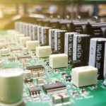
High-Temperature PCB Stability from -55°C to 125°C
A board rated for -55°C to 125°C must survive repeated swings between those limits. Each cycle expands and contracts the laminate, the copper, and the solder joints at different rates. That mismatch builds mechanical stress inside the board and at every interface. A design that passes one cold soak can still fail after a hundred cycles. Stability across this range is therefore a system property, not a single material grade.
It comes from material choice, stackup symmetry, controlled lamination, sound plated holes, and testing tied to the real profile.
Buyers often compare suppliers on laminate data sheets alone. That comparison misses most of the risk. The same laminate can produce a stable board or a failing one, depending on how the shop builds it. Resin flow, layer registration, hole-wall copper, and copper balance all shift the outcome. This guide explains the decisions that matter and the points to verify before release. It covers material selection, process control, thermal design, test coverage, and documentation. Each section ends with something an engineer or buyer can check on a real order.
Material Selection Basics
The laminate sets the ceiling for thermal performance. Glass transition temperature, decomposition temperature, and coefficient of thermal expansion are the first numbers to review. Moisture absorption and dimensional stability matter too, because absorbed moisture turns to vapor during reflow and cycling. A high Tg grade resists softening better than a standard grade, but Tg alone does not qualify a board. The full material system, including resin, glass style, copper foil, and prepreg, must suit the application. Read the data sheet against the actual temperature profile rather than a nominal range.
Z-axis expansion deserves close attention for multilayer boards. When the laminate expands through the thickness, it pulls on the plated hole walls. A material with high Z-axis CTE below Tg places more strain on those walls during cold and hot extremes. Choose a grade whose expansion curve fits the hole count and board thickness. Thin boards with many vias are more sensitive than thick, simple boards. Ask for the expansion curve, not just a single value. Then compare it with the stress your design will actually see in service.
Stackup Choices
A symmetric stackup reduces warpage and internal stress during lamination and thermal cycling. Keep copper weights and dielectric thicknesses balanced around the center line. Unbalanced builds tend to bow after reflow and drift during temperature swings. Place power and ground planes so they spread heat and support the outer layers. For high-speed boards, dielectric thickness also sets impedance, so balance and electrical needs must be solved together. Review the stackup with both thermal and signal goals in view. A short engineering review before tooling saves rework later.
Copper distribution across each layer affects local expansion and heat spread. Large copper-free areas heat and cool faster than dense copper regions, which creates local stress. Where possible, balance copper coverage and avoid abrupt changes between layers. For power designs, copper thickness, thermal vias, and heat spreading become part of the thermal plan. These choices belong in the PCB design and layout stage, before fabrication starts. Changing copper balance after the first article is built usually means a new tooling cycle and a new qualification run.
Lamination Control
Lamination turns a stack of prepreg and cores into one structure. Temperature, pressure, heat and cool rates, press time, and resin flow all affect the result. Poor control leaves voids, resin starvation, or weak bonds between layers. Those defects may pass visual inspection and still open up after thermal cycling. A good shop records the press profile for each lot and keeps it with the build record. Ask to see how the profile is set and how drift is caught.
A stable process produces the same bond strength on Monday and on Friday.
Layer registration is the other half of lamination quality. Misregistration shifts annular rings and reduces the copper that supports each hole. Under thermal cycling, a thin annular ring becomes a crack site. Check how the shop measures registration and what limits it holds. For multilayer work, registration, lamination, and drilling must be planned as one chain. GOPCBA builds high-volume PCB assembly programs where these process records follow each lot. That traceability helps when a field return needs a fast root-cause answer months later.
Drilling and Plated Holes
Plated through-holes carry most of the thermal-cycling risk in a multilayer board. Copper and laminate expand at very different rates, so the hole wall sees strain on every cycle. Hole-wall quality, desmear, electroless copper, and electrolytic copper thickness all decide how well the barrel survives. Thin or uneven plating cracks first. Ask for cross-sections from a representative lot, not just a single coupon. Look at copper thickness at the knee where the barrel meets the surface pad. That corner is where cracks usually begin.
Drilling quality sets the foundation for plating. A rough hole wall or smear left after drilling weakens the copper-to-resin bond. Resin smear must be removed cleanly without over-etching the glass. Annular ring size also matters, because a small ring leaves little copper to anchor the barrel. Check that the shop controls hole diameter, position, and wall quality as routine parameters. Edge quality matters as well. Burrs and sharp corners concentrate stress, so routing and deburring should be part of the plan for large or constrained boards.
Thermal Design and Mounting
Heat distribution inside the assembly affects long-term stability. Components, connectors, and fasteners all expand at their own rates. A board bolted rigidly at four corners cannot move when it grows, so the stress lands on joints and holes. Allow some compliance in the mounting design. Consider slotted holes, compliant standoffs, or support points placed away from sensitive areas. For power electronics, plan copper thickness, thermal vias, and heat spreading together. The goal is even temperature across the board, not just a cool spot at the hottest part.
Surface finish and solder mask also sit in the thermal path. The finish must suit the assembly process, storage conditions, and operating environment. Solder mask must keep insulation and adhesion across the full range. At high temperature, a poor mask can discolor or lose insulation. At low temperature, a brittle mask can crack. Conformal coating helps where humidity, dust, or contamination are present, but the coating must be qualified for the same temperature range. Check coating thickness, cure, and coverage as controlled parameters.
Thermal Cycling Test Coverage
Wide-range stability must be proven by test, not assumed from material data. A thermal cycling plan defines the low and high limits, dwell time, transition rate, cycle count, and acceptance criteria. Those values should come from the product specification and the applicable standard for the market. Test samples should represent the real build, including the actual stackup and hole sizes. Inspection should look for more than immediate function. Delamination, blistering, barrel cracks, and insulation drift can appear only after many cycles.
Define what counts as a failure before the test starts.
Electrical checks belong alongside the physical ones. Insulation resistance, dielectric performance, and continuity can drift as the board ages through cycles. Cross-sections after cycling show whether barrels and bonds held up. Keep the results with the lot record so a repeat order can be compared against the original. A board is qualified for a stated profile, not for every possible profile. State the profile clearly in the purchase documents. That clarity protects both the buyer and the fabricator when questions arise later.

It also makes supplier comparison fair and evidence based.
Traceability and Quality Records
Thermal reliability is built across many steps, so records must follow the board through each one. Incoming inspection should confirm material type, manufacturer, thickness, copper weight, lot number, and storage conditions. Shelf life and moisture control matter for prepreg and laminate. In-process checks should cover registration, press parameters, drilling quality, plating thickness, and final dimensions. A structured quality management system ties these records together. Without that link, a failure in the field is hard to trace back to a cause.
Documentation also supports better buying decisions. Ask for first-article reports, cross-sections, and test data before approving a lot. Confirm that the shop records which program ran and which material lot was used. These records cost little to keep and save a great deal when a problem appears. They also show whether the process is truly controlled or only described well in a brochure. Pair the records with component procurement controls, since a component change can shift thermal behavior too.
A supplier that tracks both board and parts gives a clearer reliability picture.
What to Verify Before Release
Before release, confirm the stackup is symmetric and the copper balance is reviewed. Check that the laminate data matches the real temperature profile, including Z-axis expansion. Review the press profile and registration limits for the lot. Ask for hole-wall cross-sections from a representative sample. Confirm the thermal cycling plan states limits, dwell, cycle count, and acceptance criteria. Check that mounting allows for expansion. Finally, confirm the records are complete and stored with the lot.
Each item is a concrete question with a document behind it. Together they turn a material claim into a build you can defend in the field.
For buyers moving into volume, plan the qualification run before the big order. A small pilot lot reveals stackup and process issues while changes are still cheap. Use turnkey PCB assembly only after the fabrication process is proven on that pilot. Then hold the process steady and compare each lot against the first article. Stability from -55°C to 125°C comes from repeatability, not from one good batch. The supplier that shows data, keeps records, and explains deviations is the safer choice for a long program.