How to Find Faulty Components on a PCB: PCB Design & PCB Manufacturing Guide
A printed circuit board (PCB) contains interconnected electrical and electronic circuits that enable components to communicate, distribute power, and perform specific functions. Resistors, capacitors, inductors, diodes, transistors, integrated circuits (ICs), connectors, and other components work together according to the circuit design.
When one of these components fails, the entire circuit may malfunction or exhibit abnormal behavior. A defective component can cause symptoms ranging from unstable operation and excessive current consumption to complete system failure.
For this reason, engineers and technicians need to understand how to find faulty components on a PCB efficiently. A systematic diagnostic process can help identify the source of a failure, reduce unnecessary component replacement, and restore the board to normal operation.
This guide explains common PCB component failures, essential troubleshooting tools, practical testing methods, and best practices for identifying defective components during PCB repair, maintenance, and production.
What Is a PCB Fault?
A PCB fault is an abnormal condition that prevents a printed circuit board from operating according to its intended electrical, mechanical, or functional specifications.
Common PCB faults include:
- Open circuits
- Short circuits
- Failed components
- Poor solder joints
- Damaged traces
- Defective vias
- Incorrect component placement
- Power-supply problems
- Thermal issues
- Contamination or corrosion
- Intermittent connections
Although component failure is a common cause, not every PCB problem originates from a component. A damaged trace, poor solder joint, incorrect PCB Design, manufacturing defect, or external power problem can produce similar symptoms.
Therefore, PCB Troubleshooting should begin with a systematic diagnosis rather than immediately replacing components.
Common Faulty Components on a PCB
Modern PCBs can contain hundreds or even thousands of electronic components. Each component has a specific electrical function and operating range.
Common PCB components include:
| Component | Typical Function | Common Failure Symptoms |
|---|---|---|
| Resistor | Current limiting, voltage division | Incorrect resistance, overheating, open circuit |
| Capacitor | Filtering, decoupling, energy storage | Leakage, short circuit, reduced capacitance, high ESR |
| Inductor | Filtering, energy storage | Open winding, abnormal resistance, saturation-related issues |
| Diode | Rectification, protection, switching | Short circuit, open circuit, excessive leakage |
| Transistor | Switching, amplification | Shorted junction, leakage, incorrect switching |
| IC | Processing, control, regulation | No output, abnormal current, communication failure |
| Connector | Electrical/mechanical interconnection | Intermittent contact, corrosion, physical damage |
| Fuse | Overcurrent protection | Open circuit after an overcurrent event |
The actual failure symptoms depend on the component type, circuit topology, operating conditions, and failure mechanism.
For example, a failed capacitor may cause excessive ripple in a power circuit, while a defective transistor in a switching circuit may cause abnormal current consumption or prevent the circuit from starting.
Tools for Finding Faulty PCB Components
Effective PCB Testing often requires a combination of basic and advanced instruments.
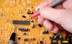
Digital Multimeter
A digital multimeter (DMM) is one of the most useful tools for PCB troubleshooting.
It can measure:
- DC and AC voltage
- Resistance
- Continuity
- Current
- Diode characteristics, depending on the instrument
A multimeter is particularly useful for identifying obvious open circuits, suspected shorts, abnormal voltage rails, and component-level problems.
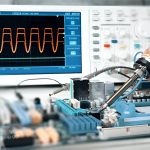
Oscilloscope
An oscilloscope allows engineers to observe electrical waveforms over time.
It is useful for checking:
- Clock signals
- PWM signals
- Analog signals
- Communication buses
- Power-supply ripple
- Transient behavior
- Oscillator outputs
When a PCB powers on but behaves incorrectly, an oscilloscope can help determine whether the expected signals are present.
LCR Meter
An LCR meter measures parameters such as:
- Inductance
- Capacitance
- Resistance
- Impedance
- ESR or related parameters, depending on the instrument
It can be particularly useful when troubleshooting passive components.
However, in-circuit measurements can be affected by parallel components, so removing the component or isolating it from the circuit may be necessary for accurate measurements.
Bench Power Supply
A programmable or current-limited bench power supply can help engineers safely investigate power-related faults.
Current limiting is especially useful when powering a board with an unknown fault because it can reduce the risk of additional damage.
Thermal Camera
A thermal imaging camera can reveal abnormal heat patterns.
It can help locate:
- Overloaded components
- Short circuits
- Failing power devices
- Hot connectors
- Abnormal current paths
- Poor thermal management
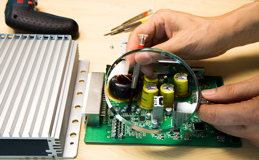
Microscope or Magnifier
High-magnification inspection is valuable for fine-pitch components, BGA areas, solder joints, traces, and small passive components.
Additional Diagnostic Equipment
Depending on the PCB, engineers may also use:
- Logic analyzers
- Component testers
- Electronic loads
- Function generators
- X-ray inspection systems
- ICT equipment
- Specialized circuit analyzers
The appropriate equipment depends on the PCB’s complexity and the type of failure being investigated.
How to Find Faulty Components on a PCB
Finding a defective component requires a structured diagnostic process. Instead of immediately removing and replacing components, begin with simple checks and gradually move toward more detailed measurements.
1. Perform a Visual Inspection
Visual inspection should normally be the first step.
Before applying power, examine the entire PCB under suitable lighting and magnification.
Look for:
- Burn marks
- Cracked components
- Swollen capacitors
- Discolored resistors
- Damaged IC packages
- Missing components
- Lifted pads
- Broken traces
- Solder bridges
- Poor solder joints
- Corrosion
- Contamination
- Loose connectors
A component that is visibly burned or cracked is an obvious suspect, but visual inspection alone cannot identify every defective component.
Many electronic components fail without leaving visible evidence.
2. Check the Power and Polarity
Before performing detailed measurements, verify that the PCB is receiving the correct power.
Check:
- Input voltage
- Power polarity
- Ground connection
- Fuse condition
- Protection circuitry
- Power connectors
- Battery connections where applicable
Incorrect input voltage or reversed polarity can create symptoms that appear to be component failures.
For example, if a board is designed for a specific regulated supply but receives excessive voltage, multiple components may be damaged simultaneously.
3. Perform Resistance and Continuity Tests
With the PCB powered off and safely discharged when applicable, use a multimeter to check suspicious circuit paths.
Useful measurements include:
- Power rail to ground resistance
- Trace continuity
- Fuse continuity
- Connector continuity
- Suspected component resistance
- Diode junction behavior
A very low resistance between a power rail and ground may indicate a short circuit, but it should not automatically be interpreted as a failed component.
Some circuits naturally contain low-resistance paths or semiconductor junctions.
Comparing the measurement with the schematic or a known-good PCB can provide much stronger evidence.
4. Measure Circuit Voltages
After confirming that it is safe to power the board, measure important voltage nodes.
Typical locations include:
- Main power input
- Voltage regulator input
- Voltage regulator output
- IC supply pins
- Reference voltage
- Analog power rails
- Digital power rails
Compare measured values with the circuit documentation.
For example, if a regulator should produce 3.3 V but its output is significantly lower, possible causes include:
- Defective regulator
- Excessive load
- Short circuit
- Incorrect input voltage
- Damaged downstream component
The abnormal voltage identifies an area for investigation, but it does not necessarily identify the failed component by itself.
5. Test Individual Components
Once a suspicious circuit area has been identified, individual components can be tested.
Resistors
Measure resistance and compare it with the nominal value and tolerance.
For accurate testing, especially in parallel networks, one terminal may need to be isolated from the circuit.
Capacitors
Depending on the capacitor type and available equipment, check:
- Capacitance
- Leakage
- ESR
- Short-circuit behavior
- Physical condition
For electrolytic capacitors, high ESR or abnormal capacitance can indicate degradation.
Diodes
Use the multimeter’s diode-test function when appropriate.
A normal diode typically exhibits a forward voltage in one direction and much higher resistance or no conduction in the reverse direction.
Transistors
Transistors can be checked for obvious shorts, abnormal junction behavior, or incorrect switching.
The exact test method depends on whether the device is a BJT, MOSFET, IGBT, or another semiconductor type.
Integrated Circuits
ICs are more difficult to test directly because they may contain complex internal circuits.
Instead of attempting to measure every internal function, engineers often check:
- Supply voltage
- Ground connection
- Clock
- Reset
- Enable signals
- Input signals
- Output signals
- Communication activity
- Abnormal temperature
If these measurements are inconsistent with the expected behavior, the IC or its surrounding circuitry may require further investigation.
6. Trace the Signal Path
Electronic components are connected through PCB traces, vias, planes, and connectors.
A defective trace can create symptoms that resemble a failed component.
Signal tracing involves identifying the expected path from the source to the destination and measuring key nodes along the way.
For example:
Power Input → Regulator → Controller → Driver → Output
By checking each stage, engineers can determine where the expected voltage or signal stops behaving normally.
For digital circuits, a logic analyzer can help identify communication failures. For analog and high-speed circuits, an oscilloscope may provide more useful information.
Signal tracing is particularly important when the components themselves appear normal but the circuit still does not operate correctly.
7. Use Thermal Testing
Thermal analysis is useful when a board exhibits excessive current consumption or unexpected heating.
After powering the PCB under controlled conditions, use a thermal camera to locate abnormal hot spots.
A hot component may indicate:
- Excessive current
- Internal component failure
- Short circuit
- Incorrect bias
- Overloading
- Poor thermal design
However, temperature alone does not prove that a component is defective. A power device may naturally operate at a higher temperature than surrounding components.
Therefore, thermal measurements should be combined with electrical measurements.
8. Compare with a Known-Good PCB
When available, a known-good PCB can be extremely useful for troubleshooting.
Compare:
- Resistance values
- Power-rail voltages
- Component temperatures
- Signal waveforms
- Current consumption
- Communication behavior
This approach can quickly highlight abnormal areas, particularly when the original schematic or detailed documentation is unavailable.
PCB Component Fault Identification Best Practices
Once a suspicious component has been identified, follow a controlled repair and verification process.
Follow the Original Design Documentation
Use the approved schematic, PCB layout, BOM, and applicable manufacturing documentation whenever possible.
Avoid making assumptions about circuit operation based solely on physical appearance.
Power Down Before Resistance Testing
Resistance and continuity measurements should normally be performed with the PCB unpowered. Capacitors and other stored-energy circuits should be discharged using an appropriate procedure before handling.
Use ESD Protection
Use appropriate ESD controls when working with sensitive semiconductor devices.
This may include:
- ESD wrist straps
- Grounded workstations
- ESD mats
- Suitable component-handling procedures
Record Every Measurement
Maintain a troubleshooting record containing:
- Measurement location
- Measured value
- Expected value
- Instrument used
- PCB revision
- Component reference designator
- Test condition
This information can make future troubleshooting significantly easier.
Start with Simple Causes
Do not immediately assume that a complex IC has failed.
First check:
- Power
- Ground
- Connectors
- Fuses
- Solder joints
- Obvious physical damage
- Component orientation
Simple faults are often easier to identify and can produce symptoms that appear much more complicated.
Replace Components with Correct Specifications
When a component is confirmed to be defective, the replacement should match the required electrical, mechanical, thermal, package, and reliability specifications.
For production repairs, component traceability and approved replacement procedures should also be considered.
Avoid Unnecessary Rework
Repeated soldering and desoldering can damage pads, vias, solder mask, and the PCB laminate.
Only perform the level of rework necessary to confirm the diagnosis and complete the repair.
PCB Design and Manufacturing Factors Affecting Component Reliability
Component reliability does not depend on the component alone.
During PCB Design, engineers should consider:
- Component operating temperature
- Current and voltage ratings
- Thermal dissipation
- Power distribution
- Trace width
- Grounding
- Decoupling
- Component spacing
- Signal integrity
- Mechanical stress
During PCB Manufacturing and PCB Assembly, additional factors include:
- Component quality
- Solder-paste printing
- Component placement
- Reflow profile
- THT soldering
- Cleaning requirements
- Solder-joint quality
- Inspection
- Electrical testing
A defective component may therefore be the result of component aging, electrical overstress, thermal stress, mechanical damage, or an assembly/manufacturing problem.
Understanding this relationship helps engineers avoid treating every PCB failure as an isolated component problem.
Common Mistakes When Finding Faulty PCB Components
Several troubleshooting mistakes can make diagnosis slower or even create additional damage.
Replacing Components Without Testing
Replacing multiple components at random can make it difficult to determine the actual root cause.
Test first whenever practical.
Testing a Powered Board in Resistance Mode
Do not use resistance mode on an energized circuit. This can produce incorrect readings and may damage the instrument or circuit.
Ignoring the Circuit Diagram
Component measurements have to be interpreted in circuit context. The schematic and PCB layout provide essential information about expected connections.
Assuming the Hottest Component Is the Failed Component
Thermal hotspots are useful clues, but some components are designed to dissipate significant power.
Always confirm thermal findings with electrical measurements.
Overusing Soldering Equipment
Excessive heat can damage pads, vias, components, and PCB materials.
Use appropriate temperature control and rework techniques.
Ignoring Intermittent Failures
Some faults only appear under vibration, temperature changes, mechanical stress, or load.
If the board works intermittently, investigate connectors, solder joints, vias, traces, and temperature-dependent behavior rather than focusing only on permanently failed components.
Conclusion
Learning how to find faulty components on a PCB requires more than simply checking individual components with a multimeter. Effective PCB Troubleshooting combines visual inspection, power verification, resistance and continuity testing, voltage measurements, component-level analysis, signal tracing, and thermal inspection.
The most reliable approach is to start with simple observations and measurements, identify the abnormal circuit area, and then progressively narrow the diagnosis to the component or connection responsible for the failure.
PCB Design and PCB Manufacturing also play important roles in component reliability. Appropriate component selection, thermal management, layout, assembly quality, inspection, and electrical testing can all reduce the risk of premature failures.
Whether troubleshooting a prototype, repairing a field-returned product, or investigating a production defect, a systematic diagnostic process helps engineers identify faulty components more efficiently while minimizing unnecessary rework and replacement.
For professional PCB manufacturers such as Kingda, integrating reliable PCB Manufacturing, PCB Assembly, inspection, and testing processes provides an important foundation for consistent product quality and long-term reliability.