IPC Class 2 vs Class 3 PCB: Key Differences and Standards
Two boards can leave the same shop with identical copper and still be judged by different rules. The IPC class decides which acceptance limits apply to holes, solder joints and surface features. It also shapes how much process control the job needs. Buyers who treat the class as a label miss the point, because the class drives real decisions on the floor.
The choice belongs in the drawing and the purchase order, not in a conversation after delivery. Engineers should confirm the class before tooling starts. Inspectors then apply the same criteria at every build. That shared reference is what keeps a first article and a repeat order comparable.
What the Classes Mean
IPC classes describe performance expectations for the finished product. Class 2 covers dedicated-service electronics where continued performance and extended life matter. Class 3 covers high-reliability products where continuous operation is critical. The difference is not a single inspection step. It is a set of acceptance requirements applied across fabrication and assembly.
The class follows the application, not the other way around. A product used in a normal office has different consequences of failure than a product used in a hospital. Engineers should state the intended environment and service life in the project file. That statement then justifies the class and the inspection plan that follows it.
Class 2 Requirements
Class 2 boards serve telecom, industrial control, test instruments and commercial equipment. Continued performance and a reasonable service life are the goals. Some defects may be acceptable when the applicable criteria permit them. That allowance does not remove the need for controlled materials, plating, soldering and cleanliness.
Buyers often ask whether Class 2 means lower quality. It does not. It means the acceptance limits match a dedicated-service product. A well-built Class 2 board can run for years in the right environment. The key is to confirm the limits in writing and to verify them with records, not with a visual impression.
Class 3 Requirements
Class 3 applies to medical, aerospace and mission-critical systems. Continuous operation is often essential, and failure carries serious consequences. Acceptance requirements are therefore more restrictive. Conditions that pass under Class 2 may fail under Class 3 because they reduce long-term reliability.
This tighter stance reaches plated holes, annular rings, conductor integrity and solder joints. It also raises expectations for process control and traceability. A supplier should be able to show which parameters ran, which materials were used and what inspection found. Those records support the class claim better than any brochure statement.
Copper and Hole Quality
Conductor width, spacing and integrity are checked against the selected class. A defect that thins a trace may look minor but can affect current capacity and fatigue life. Class 3 work usually demands closer evaluation of such conditions. Class 2 work still needs the trace to meet the drawing.
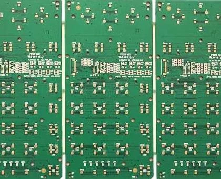
Plated through-holes carry current and mechanical load between layers. Inspectors review plating thickness, hole wall condition, voids, cracks and annular ring. Class 3 limits are tighter because a failed interconnection can take down a whole system. Cross-sections help confirm what the eye cannot see.
Drilling sits upstream of every hole limit, so it deserves attention early. A worn bit or a fast feed rate can smear the resin and tear the copper at the hole wall. Plating then covers a weak surface instead of bonding to sound material. Thermal cycling later opens that weakness into a crack. Buyers should ask how drill bits are counted and retired, and whether hole quality is sampled by cross-section after plating.
Etching and plating control decide whether the finished trace matches the drawing. Over-etching narrows conductors and reduces the margin the designer intended. Thin plating raises resistance and lowers fatigue life in vibrating equipment. Both effects hide under solder mask and pass a quick look. A supplier that tracks line width and plating thickness as routine data can show the trend before a lot drifts out of limits.
Solder Joints and Surface Finish
Joint acceptance depends on component type, assembly technology and the applicable assembly standard. Coverage, wetting, voids and alignment all matter. Class 3 usually leaves less room for conditions that could shorten field life. Class 2 still requires joints that meet the drawing and the process specification.
Surface finish affects solderability, contact performance and durability. High-reliability products may need tighter control and qualification of the chosen finish. Buyers should confirm the finish on the fabrication drawing and check that the assembly process suits it. Finish and paste choices interact, so they belong in one review.
Lamination control is easy to overlook until a board fails in the field. Trapped moisture, low press pressure or a poor cure can leave voids and weak bond strength between layers. The defect often survives electrical test and only appears after thermal stress. Class 3 programs usually expect tighter press parameters and a coupon for bond integrity. Buyers should confirm that lamination records exist and that panels are baked before pressing when the material requires it.
Why Appearance Is Not Enough
Class 3 does not simply mean a board looks better. Two boards can appear identical while carrying different internal conditions. Internal copper thickness, interlayer registration and lamination quality only show up in cross-section. Hole-wall defects and internal separation are equally hidden from normal visual checks.
Acceptance should rest on the applicable standard, the fabrication drawing and agreed inspection methods. A supplier that judges class by appearance alone will miss the conditions that matter most. Ask for the inspection plan and the records behind it. That evidence shows whether the class was applied or only mentioned.
Registration errors tell the same story from another angle. A mask opening that drifts onto a pad can expose copper to solder and create a bridge. A silkscreen that shifts onto a solderable area can block wetting. Neither shows as a cosmetic flaw in a photo. Inspectors need the artwork tolerances and a clear rule for what counts as a defect under the chosen class.

Choosing the Right Class
Class 2 fits products in conventional environments where occasional service interruption is tolerable. Class 3 fits products where continuous operation is essential and failure creates safety or operational risk. The decision should be recorded in the specification before quoting. Changing class later usually forces new limits, new records and sometimes new tooling.
Building to Class 3 when the product does not need it can add cost without a real benefit. Building to Class 2 when the application demands more is a risk that surfaces in the field. Match the class to the consequence of failure, then hold that decision through every lot. Our quality management process keeps those limits visible from first article to shipment.
Verification and Buying Checks
Confirm the specified class and the standards that apply. Review drawings, stackup and material requirements before release. Check conductor, mask and hole characteristics against the agreed limits. Verify the finish and run dimensional and electrical checks where the plan requires them.
For production orders, agree the acceptance criteria before manufacturing starts. Inspection data, cross-sections and test results should travel with the lot. Teams moving from samples to volume should plan rapid PCBA prototyping early, so process behavior is known before the big order. Assembly and test records then confirm the class claim in practice, and SMT PCB assembly controls keep joints within the agreed window.
Test coverage closes the loop between inspection and process control. Electrical checks catch cracked joints and wrong parts that visual review cannot find. A structured PCBA testing plan gives buyers evidence that the class was met on every board. High-reliability programs also need stable output at scale, which is why high-volume PCB assembly should share the same acceptance criteria as the pilot run.
Supplier audits should follow the same logic. Ask to see how a nonconformance is written, who reviews it and how the fix reaches the next lot. A factory that closes issues with data will usually hold a class limit through a long run. A factory that answers with reassurance alone will drift once the first article is forgotten. The questions cost little and reveal a great deal about daily practice.
The practical takeaway is simple. Write the IPC class into the drawing and the purchase order, agree the inspection limits before tooling, and require the records with every lot. That combination turns a class designation into a verifiable result.