Automatic Optical Inspection Programming in Production
An automatic optical inspection system is only as good as the program it runs, and the program is built from CAD data, a component library and a set of thresholds that decide what is acceptable. Programming is therefore where the inspection yield, the false call rate and the escape rate are all determined, long before the first production panel is scanned. A well built program runs for years with almost no attention, while a badly built one consumes an operator for a full shift every day.
What the Program Has to Detect
The system has to find missing components, wrong components, reversed and rotated parts, misalignment beyond a limit, wrong polarity, bridging and insufficient or excess solder. Each of those is detected by a different algorithm, and each needs its own reference data.
The program also has to ignore the things that do not matter, such as a variation in legend print or a slight difference in mask colour. Every false call costs operator time, and a high false call rate is the fastest way to make a line stop trusting the inspection system. Once operators begin to clear calls without looking, the system has stopped providing any protection at all.
Data Inputs and CAD Translation
The starting point is the CAD data from the design, which gives the position, rotation and package type of every component. The data has to be translated into the coordinate system of the machine and verified against the actual artwork.
Discrepancies between the CAD model and the manufactured board are the most common source of a badly placed inspection window. A component that is listed on the wrong side of the board, or a footprint that does not match the library, will produce either a false call or a missed defect. Verifying the translation against a physical board before the program is released is a step that is often skipped and rarely regretted. Our AOI guide covers the general use of the technology. The translated data should be checked against the placement program, because the two are built from the same source and any difference indicates a problem in one of them.

Building the Component Library
The library holds the reference images and the parameters for each package type. A package that is not in the library has to be taught, and the quality of that teaching decides how well it is inspected on every board that follows.
Teaching is best done from a known good board that has been verified by an operator, because the algorithm compares what it sees with what it was shown. A library built from a board with a defect will look for the defect rather than for the correct result. Library entries should be reviewed by a second person, because an error in a library is repeated on every board that uses it.
Setting Inspection Windows
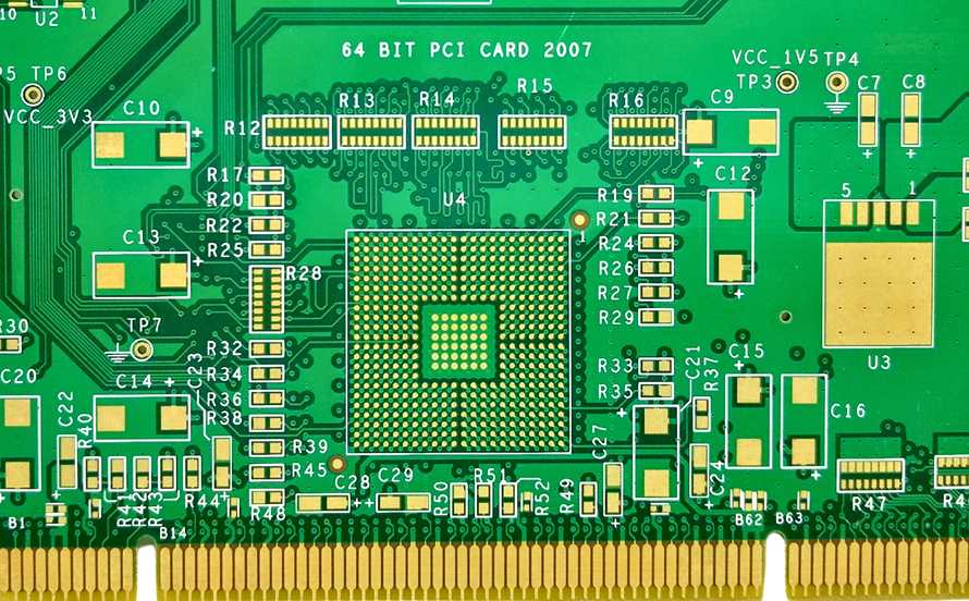
The window around a component defines where the algorithm looks, and its size is a compromise. A window that is too small misses a component that has moved, while one that is too large includes neighbouring features that confuse the comparison.
The window also has to account for the placement tolerance of the machine and for the movement of the board in the conveyor. Where the board is not well clamped, a window that works at the start of a run may fail later in the same run. Board support is therefore part of the inspection setup and not only part of the printer setup.
Thresholds and False Calls
Every algorithm has a threshold, and where that threshold is set defines the trade off between escapes and false calls. A tight threshold finds more real defects and rejects more good boards, while a loose one does the opposite.
The correct setting is found by measuring both numbers on a known sample, not by adjusting until the line stops complaining. A false call rate that is too high is usually a library or window problem rather than a threshold problem. Recording both the escape rate and the false call rate over time shows whether the program is improving or drifting. Our quality documentation describes how these results are classified at gopcb.
First Article and Debug
The program is proven on a first article that is inspected visually and, where necessary, by X-ray. Every call the system makes is reviewed, and both the false calls and any defect it missed are added to the debug list.
That process takes time and it is the only reliable way to build a program that finds real defects. A program that is released without a first article debug will spend its first weeks producing calls that nobody trusts. The debug record should be retained, because it is the evidence that the program was validated rather than merely loaded.
Program Maintenance and Change Control
The program is a controlled document and should be versioned like one. A change to the layout, the package, the paste or the placement machine all affect the inspection, and each change should trigger a review of the relevant part of the program.
Where a program is copied between products without review, the library entries and the thresholds travel with it, and so do any errors that were tuned to suit the original product. Copying a program is a reasonable starting point, provided the library, the windows and the thresholds are all reviewed against the new board. Our production flow guide places the inspection step in the wider sequence. Change control on the program is what keeps the inspection result comparable between lots.
Limits of Optical Inspection
Optical inspection sees the surface and nothing else. It cannot evaluate a solder joint under a package, a via that is filled, or a joint that has wetted properly but looks unusual because of the finish. A program that is tuned to reject unusual looking but acceptable joints will produce a steady stream of false calls.
Those limits are why optical inspection is normally combined with X-ray for area array packages and with electrical test for the electrical function. Choosing the combination is the same fault spectrum exercise that applies to the whole test strategy. Our X-ray guide compares the two inspection methods directly. The combination should be chosen from the fault spectrum, and the coverage of each method should be documented.
Process Control Points
The controls are the CAD revision used to build the program, the library revision, the window and threshold settings, the first article debug record and the version of the program currently loaded on the machine. The four items are simple to record and between them they cover almost every cause of an inspection escape.
Verifying that the loaded program matches the product being run is perhaps the most important single check, because a board inspected with the wrong program passes without being examined at all. A scanner at the start of the line that reads the product barcode is a simple and effective way to enforce it. Inspection programming is therefore as much a documentation discipline as a technical one.
FAQ
Why does the inspection system produce so many false calls? Usually because the library was taught from a poor sample or the inspection windows are too large. Threshold adjustments often hide the real cause rather than fixing it.
Can optical inspection find a hidden solder joint? No. It sees only the surface, so joints under an area array package have to be checked with X-ray or by electrical test.
How often should the program be reviewed? Whenever the product, the package, the paste or the placement machine changes. Treating the program as a controlled document is what keeps the inspection meaningful.