Mixed Signal ADC Layout and Grounding
What the Converter Needs
A high resolution converter resolves a voltage in the microvolt range, and the layout has to deliver that voltage to the input without adding noise or an error. The two things that ruin a converter’s performance are a noisy reference and a ground that carries the digital return current. Both are layout problems, and both are invisible in a schematic. The design should be arranged so that the analogue signal, the reference and the analogue return form a small, quiet loop, and the digital currents are kept out of it.
The Analogue Input and Its Return
The analogue input should be routed as a pair with its return, kept short and away from the digital signals, and referenced to the analogue ground rather than to the plane in general. Where the source is remote, a differential pair with a shielded or a guarded routing is used, and the pair’s return should be the analogue ground, not the digital ground. The input’s filter components should be placed close to the converter rather than at the source, so that the noise they remove does not travel along the trace. A single ended input with a long trace and a distant return is the classic way to lose several bits of resolution.
The Reference
The reference sets the conversion, so any noise on it appears directly in the result. The reference should be a quiet source, decoupled close to the converter with a low impedance capacitor, and its return should be the analogue ground. Where the reference is shared with another circuit, the shared current produces a voltage drop that appears as an error, so a dedicated reference or a buffer is often justified. The reference’s trace should be short and should not run alongside a digital line, and the capacitor’s placement should be the shortest possible path to the converter’s pin and to the ground.
Grounding and the Split
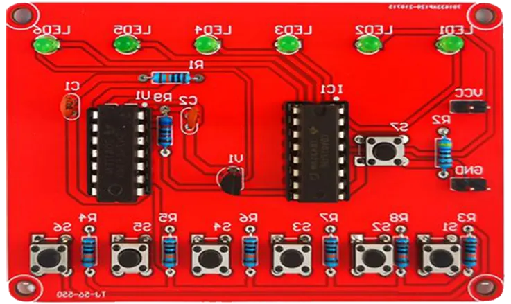
The traditional advice is to split the analogue and digital grounds and to join them at a single point under the converter. The principle behind it is correct: the digital return current must not flow through the analogue reference. Whether the split is the best implementation depends on the design, because a split that forces a signal to cross a gap creates its own problem, and a continuous plane with careful placement often performs better. The rule that should be kept regardless is that the digital return paths must not pass under the analogue section, and the layout has to make that true rather than assume it.
Placement and the Sections
The layout should have a defined analogue area and a digital area, with the converter at the boundary. The analogue components go in the analogue area, the digital ones in the digital area, and the converter’s pins are arranged so that its analogue pins face the analogue side and its digital pins face the digital side. The clock and the data lines then leave the converter into the digital area without crossing the analogue one. A layout that mixes the two, or that puts a switching supply in the analogue area, will produce a performance that no amount of filtering will recover.
Clocking and Digital Noise
The converter’s clock and its data interface are the main digital noise sources, and their return current is the problem. The clock line should be short, terminated where the frequency requires it, and routed away from the analogue input. The data lines should be routed together with their return and should not pass under the analogue area. Where the converter’s digital interface is a serial one, its speed and its edge rate should be the lowest that the throughput allows, because a slower edge radiates less. The converter’s own digital outputs should not be routed near its analogue input, since the coupling is direct and immediate.
Verification
The layout should be verified by measuring the converter’s performance rather than by inspecting it. Effective number of bits, signal to noise ratio and total harmonic distortion at the frequencies of interest are the parameters, and they should be measured with the actual sources and the actual clock. A measurement with the input shorted shows the noise floor, which is the quantity that the layout most affects. A comparison between the board and a reference design, or between two layout variants, is far more informative than a single number, and it shows whether the layout is the limiting factor.
Test Access for the Analogue Section
The analogue section needs to be measurable, which means test points that do not disturb it. A test point on the analogue input adds a stub and a capacitance, so it should be placed where it does not degrade the signal, or it should be buffered. The reference should have a test point that can be measured without loading it, and the ground reference for the measurement should be available next to it. Where the converter is on a board that will be produced in volume, the test points allow the analogue performance to be verified per unit, which is the only way to catch a manufacturing variation in a component that matters.
FAQ
What limits a converter’s accuracy? Usually a noisy reference and a ground that carries the digital return current, both of which are layout issues.
Should the grounds be split? The principle is to keep the digital current out of the analogue reference; whether a split or a continuous plane achieves it depends on the design.
Where should the input filter be? Close to the converter, so the noise is removed at the point where it matters.
Why keep the digital lines away from the analogue input? Because the coupling is direct and no filtering afterwards can remove it.
How is the layout verified? By measuring the noise floor with the input shorted and the signal to noise ratio with a real signal.
Conclusion
A converter’s accuracy is decided by the reference and the return paths, so define the sections, keep the digital current out and place the filter where it acts. Measure the noise floor. Mixed signal layout belongs to PCB design and layout, the assembly sits in PCB assembly, and the verification is part of PCBA testing. Mixed signal boards are first built during prototype PCB assembly in 2026.