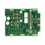
PCB Antennas: Clearance and Layout Rules
How a PCB Antenna Works
A printed antenna is a copper pattern whose dimensions and surroundings set its resonant frequency and its impedance. Because it is etched on the same board as the rest of the circuit, its performance depends on things that would not matter to a connectorised antenna: the copper plane beside it, the plastic of the enclosure, the battery behind it and the presence of a hand or a body. A design that copies an antenna pattern without copying its surroundings will not tune where the reference design tuned, and the difference can be tens of megahertz.
The Ground Clearance
The single most important layout rule is the ground clearance, the area beneath and around the antenna where no copper is permitted on any layer. The antenna radiates by using the ground plane as its counterpoise, so the boundary between the keep-out and the plane is part of the radiating structure. A plane that encroaches into the keep-out detunes the antenna and reduces its efficiency, and a plane that is absent where it should be removes the counterpoise. The keep-out must extend through every layer, including inner planes, and the requirement should be drawn as a rule area rather than described in a note, because it is easy to fill that space with a plane during a later edit.
Feed and Matching
Most printed antennas are fed by a microstrip line from the radio, often with a matching network of a few components placed close to the feed point. The feed line is a controlled-impedance line and it should be kept short, since every millimetre adds loss and shifts the matching. The matching components should be placed so that they can be changed without disturbing the antenna itself, and their pads should be sized for a hand or a rework operation if prototypes are expected to be tuned. Where the radio has a balun, the transition from the differential output to the single-ended antenna feed is a design element in its own right and should be modelled rather than guessed.
Placement on the Board
The antenna belongs at the edge of the board, on a corner if possible, with the keep-out extending off that edge. Placing it in the middle of a board surrounds it with copper and with components, both of which reduce its efficiency and change its tuning. The orientation matters as well: the antenna should be placed so that its polarisation suits the way the product will be held and used, which is a system decision as much as a layout one. Where the design has more than one radio, the antennas have to be separated enough that they do not couple, and where they operate in the same band the separation requirement is significant.

Effects of the Enclosure
Plastic changes the effective dielectric constant at the antenna, lowering its resonant frequency, and the amount depends on the material and on how close it is to the pattern. A battery behind the antenna, particularly a metal-cased one, detunes it further and absorbs energy, which is why the antenna is normally placed at the opposite end of the board from the battery. A metal enclosure or a metallised coating, which is increasingly used to shield a product, will block the antenna entirely unless a deliberate opening or a plastic window is provided. These effects are large enough that the antenna should be tuned in the final mechanical configuration, not on a bare board.
Materials and Thickness
The board material under the antenna affects the tuning, since the dielectric constant and the thickness set the guided wavelength that the pattern is designed around. Moving from one laminate to another with a different Dk shifts the resonant frequency, and moving to a thinner board does the same. Where the design has to work on more than one stack, the antenna should be tuned on the stack that will be used in production, and a change of material should be treated as a design change rather than a purchasing decision.
Tuning and Verification
Tuning is done by measuring the reflection coefficient with a network analyser or a vector analyser and comparing the resonant frequency and the bandwidth with the target. The measurement should be made with the product in its final mechanical state, since the presence of a hand, a case or a battery changes the result. Where an anechoic chamber is not available, a return-loss measurement gives the tuning, and the efficiency has to be inferred from the pattern or from a comparative range test. The useful design practice is to include a pi-matching network at the feed so that the antenna can be corrected at the last stage without changing the artwork.
Antennas in a Product Family
Where several products share a board or a family of boards, the antenna is usually the element that forces the most re-work, because each mechanical variant has a different enclosure, a different battery position and a different ground plane area. The practical answer is to standardise the antenna keep-out and the matching network across the family, so that a variant changes only the tuning components rather than the artwork. This requires the keep-out to be treated as a hard constraint in the layout tool, and the matching network to be placed where it can be reworked without disturbing the rest of the radio. Where a product is expected to be tuned in production, the design should also state the test method and the fixture, because a tuning step that cannot be measured in the factory is a step that will be skipped. Treating the antenna as a component with its own specification, rather than as a copper pattern that happens to be on the board, is what makes it repeatable across a product line.

FAQ
Why does my antenna not tune where the reference design tuned? Because its surroundings differ. Ground clearance, enclosure material, battery and board thickness all shift the resonant frequency.
How much clearance is needed? It depends on the antenna, but the keep-out must extend through every layer and past the board edge, and it is normally specified by the antenna vendor.
Should the antenna be tuned on a bare board? No. It should be tuned in the final mechanical configuration, since the enclosure and the battery change the result.
Can a metal enclosure be used? Only with a deliberate opening or a plastic window, otherwise the antenna is shielded from the outside world.
Why include a matching network? So that the antenna can be corrected at the last stage without changing the copper pattern.
Conclusion
A printed antenna is defined by its surroundings as much as by its geometry, so the ground clearance, the enclosure and the nearby parts are all part of the design. Draw the keep-out as a rule area on every layer, keep the feed short, place the antenna at an edge away from the battery, and tune the prototype in its final mechanical state. Radio layout rules belong to PCB design and layout, the materials that the tuning depends on are listed under PCB capabilities, and the assembly of the radio module is covered by SMT PCB assembly. Antenna performance is normally confirmed during prototype PCB assembly in 2026.