
Assembly Drawing and Notes for PCB Production
An assembly drawing is the document that tells the factory what the designer intends. When it is complete, the operator never has to guess; when it is thin, every guess becomes a defect that someone has to explain later.
Most assembly problems that are blamed on the process turn out to be ambiguity in the drawing. A polarity mark that exists only in the CAD file, a note that says “as required” or a missing stack up means the factory has to invent an answer, and the invented answer is rarely the one the designer had in mind.
What the Drawing Must Carry
The drawing should show the board outline with dimensions, the reference designators, the polarity of every polarised part and the position of any part that has a restricted orientation. It should identify the assembly side for each operation and state the sequence where a board is built in more than one pass.
It should also carry the notes that no CAD export contains: the solder alloy, the flux type where it is specified, the cleaning requirement, the conformal coating requirement and the acceptability standard that the finished joints will be judged against.
Bill of Materials and Approved Substitutes
The bill of materials is only useful when each line identifies the part precisely enough to be ordered, including the tolerance, the package, the temperature rating and the plating. A part number that resolves to three different suppliers with different packages will eventually be filled with the wrong one.
Approved substitutes should be listed explicitly, with the characteristics that must match. A generic note permitting an equivalent part transfers an engineering judgement to the buyer, and that judgement is usually made on price rather than on the parameters that matter.
Revision Control and Marking
Every board should carry a revision identifier that the factory can read, and the drawing should state where that identifier is placed and how it is marked. A board that has been changed without a visible revision cannot be identified on the line, and mixed revisions in one batch are almost impossible to sort afterwards.
Where the revision is marked on the copper rather than on the silkscreen, the note should say so, because a coated board hides the copper and the revision becomes invisible at the point where it is most needed.
Fabrication Notes and Stack Up
The assembly drawing references the fabrication documentation rather than repeating it, and the two documents should be consistent. Impedance requirements, copper weights, the stack up and the surface finish are fabrication information, but the assembly process depends on all four.
Surface finish is the clearest example, since a finish chosen for shelf life behaves differently in the paste and in the reflow profile than one chosen for fine pitch. The assembly drawing should state the finish it was validated with so that a substitution is a deliberate decision.
Special Process Instructions
Where a part cannot survive a standard profile, the drawing has to say so and give the alternative. Where a connector is added after reflow, where a shield can is soldered by hand or where a component is staked, those operations belong on the drawing with their materials and their order.
Special instructions cost less than a process engineer’s time to discover them. A short section listing the exceptions to the standard process is the most valuable part of an assembly drawing on a mixed technology product.
Inspection and Acceptance Criteria
The drawing should name the standard that the inspection follows rather than describing it in words, and it should note any class requirements that are more demanding than the default. Where a joint class differs between areas of the same board, the areas should be identified.
Acceptance criteria also cover the cosmetic items that are otherwise argued about: whether flux residue is acceptable, whether a small scratch on a coating is a defect and how much discolouration of a laminate is allowed. Written criteria end the debate before it starts.
Panel and Test Information
Assembly drawings for panelised products should show the panel layout, the breakaway method and the position of the fiducials. The test department needs the same information, because a flying probe programme is written from the panel layout rather than from a single board.
Where boards are serialised, the drawing should state the marking method and the position, since a serial number that is applied over a joint or inside a coating area creates a problem for both the marking step and the inspection step.
Packaging and Delivery
Packaging requirements belong on the drawing when the parts are sensitive to moisture, to static or to mechanical damage. A drawing that says nothing about packaging leaves the choice to the shipper, and the shipper optimises for cost.
Where the boards are moisture sensitive, the bag, the desiccant and the indicator card should be named, and the floor life should be stated so that the receiving inspection knows what it is checking. This is the same information that drives the schedule described for moisture bake decisions.
Reviewing the Pack Before Release
The final check is a walk through the drawing as if building the product for the first time, asking at each step what the factory would do with the information shown. Any step that requires knowledge held only by the designer is a gap.
Reviewing the drawing against the design release checklist and the fabrication notes catches most of the gaps before tooling is committed. The cost of the review is an hour, and the cost of the gap is a batch.
Process Control and Verification
On a design of this kind, bill of materials is the item that decides how the rest of the board is arranged. The process window is set by the narrowest step in the flow, so an improvement anywhere else shows up as margin rather than as yield until that step is addressed. A short note on the drawing about handling, storage or packaging is often worth more than an extra decimal place on a tolerance.
Where a value sits close to a process limit, the drawing should say so, since the shop can then open the process window rather than working to a nominal figure that carries no tolerance.
Related reading: our fabrication notes, board quality and design release notes cover the same ground.
Process Control and Verification
On a design of this kind, bill of materials is the item that decides how the rest of the board is arranged. The process window is set by the narrowest step in the flow, so an improvement anywhere else shows up as margin rather than as yield until that step is addressed. A short note on the drawing about handling, storage or packaging is often worth more than an extra decimal place on a tolerance.
A first article check confirms that the process and the drawing agree on the points listed above, and that the coupon data supports the values used in the design.
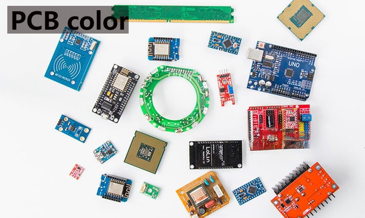
Where a measurement falls outside the expected window, the sample is retained so that the cause can be established before the balance of the batch is released.
A first article check confirms that the process and the drawing agree on the points listed above, and that the coupon data supports the values used in the design.
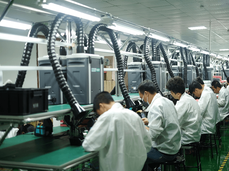
Where a measurement falls outside the expected window, the sample is retained so that the cause can be established before the balance of the batch is released.
FAQ
Is a CAD file alone enough for assembly? No. The CAD file carries geometry, while the drawing carries intent, and the intent is what the operator follows when something looks unusual.
How much detail about the process belongs on the drawing? All of it where the process affects the result, and none of it where the standard process already covers the requirement.
Who should sign the assembly drawing? The engineer who owns the design, with the assembler consulted on the process notes, because those notes are where the factory adds its knowledge.
How often should the drawing be revised? Whenever the board, the parts or the process change, and the revision should be visible on the copper or the silkscreen so the change can be identified on the line.