Clock Distribution Design for PCB Layouts
A clock is the signal that every synchronous part of the board depends on, and it is also the one most easily degraded by the layout. Clock distribution covers the choice of source, the way the clock is routed to the devices that need it, and the control of the two properties that decide whether it works: skew, which is the difference in arrival time between destinations, and jitter, which is the variation in the period. Both are affected by decisions made during layout rather than by the clock generator alone.
Planning the Clock Tree
A clock tree describes where each clock originates and how it reaches its destinations. The choices are fundamental: a single source buffered to many points, several independent sources, a clock generator with multiple outputs, or a recovered clock from a data stream. The choice determines the skew that can be achieved and the amount of routing that has to be controlled.
Fan-out is the central question. A source that drives many loads through a single point creates a large load and a slow edge, and the usual answer is a buffer tree with each branch driving a limited number of destinations. Each buffer adds its own delay and its own jitter, so the tree should be as shallow as the loading allows, and the buffers should be placed so that the branches are similar in length.
Devices that generate their own clocks internally change the picture, because their outputs may need to be synchronised with an external reference. Where a clock has to cross between domains, the phase relationship should be defined in advance, and the design should either control the skew between the two paths or provide a mechanism for the receiving logic to tolerate the difference.
Skew and Length Matching
Skew is the difference in arrival time of the same clock at different destinations, and it is controlled by matching the electrical length of the paths. Length matching is the practical method, but the electrical length depends on the propagation velocity of the trace, which depends on the material and the geometry rather than only on the physical distance.
Matching should be done between the paths that matter, which usually means the destinations that sample the same data or the clock and its associated strobe. Matching every clock to every other clock is unnecessary and consumes routing space. The correct scope is the group that has a timing relationship in the design.
Layer changes affect skew because a signal that travels partly on an outer layer and partly on an inner layer has different propagation delays, and vias add both delay and a small discontinuity. Where matching has to be tight, keeping the paths on the same layer and using the same number of vias is more reliable than adding serpentine length to compensate.
Jitter and Its Sources
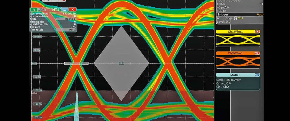
Jitter is the variation in the timing of the clock edges, and it comes from the source, from the power supply and from the interconnect. The oscillator or the phase locked loop contributes its own jitter, which is specified by the manufacturer, and the supply noise modulates the switching thresholds of the buffers and the receivers, converting voltage noise into timing noise.
The interconnect contributes jitter through loss and through crosstalk. A trace that attenuates the high frequency content slows the edge, and a slow edge is more sensitive to noise because the receiver spends longer in the region where the threshold is being crossed. Crosstalk coupled onto a clock produces the same effect, which is why clocks should not run parallel to switching signals for long distances.
Power supply noise is the term most under the designer’s control. A clean supply for the clock buffers, with local decoupling and a low impedance path to the reference plane, reduces the conversion of supply noise into timing variation. Where the clock is critical, a separate low noise regulator for the clock section is a common and effective measure.
Routing Practice
Clock traces should be routed over a continuous reference plane, with a controlled impedance where the length or the frequency requires it, and away from sources of noise. The plane is essential because the return current follows the trace, and a plane that is split beneath the trace forces the return current into a long detour, which increases the loop area and the emissions, and degrades the edge.
Crossing a plane split is one of the most common layout errors. Where a clock must change reference planes, a stitching capacitor or a via arrangement near the crossing provides a return path, and the measure should be deliberate rather than accidental. Where the design allows it, the simpler answer is not to cross.
Termination is applied to clocks in the same way as to other fast signals. A series resistor at the source is the most common measure, and it also slows the edge slightly, which reduces emissions. A parallel terminator at the end is used where the clock feeds a single destination and matching is critical. The choice should follow the driver, the topology and the number of loads.
Measurement and Verification
Verification of a clock is a measurement task, and it needs a probe with adequate bandwidth and a ground connection that is short. A long ground lead adds inductance that distorts the displayed edge, and a probe with insufficient bandwidth will show a clean clock that does not exist. The measurement should be made at the receiver rather than at the source, because that is where the timing matters.
Skew is measured by comparing the arrival times at the destinations, which requires several probes or a repeated measurement with a stable trigger. Jitter is measured over many cycles, and the relevant figure is usually the peak to peak value at a defined number of cycles rather than the cycle to cycle value alone.
The measurements should be made over temperature and supply extremes, because both affect the oscillator and the buffers. A clock that is comfortable at room temperature can lose margin at the extremes, and the loss appears as an intermittent data error rather than as a clock failure, which makes it far harder to find later.
Special Cases
Differential clocks are used where jitter and noise immunity matter, and they require the same care as any differential pair: matched lengths, a constant spacing, and a reference plane beneath both traces. The two sides of the pair should be treated as one signal in the layout, and the pair should not be split between layers more often than necessary.
Spread spectrum clocks modulate the frequency slightly to reduce emissions, and they require the receiving device to tolerate the modulation. Where the modulation is not tolerated, the link may fail intermittently, so the compatibility should be confirmed before the design is released rather than discovered during testing.
Clock recovery from a data stream removes the need to distribute a separate clock, at the cost of complexity in the receiver. Where it is used, the jitter budget has to include the recovery circuit, and the quality of the incoming data eye becomes the limiting factor rather than the clock distribution itself.
Practical Rules
Plan the clock tree before layout, match the lengths of the paths that have a timing relationship, and route clocks over a continuous reference plane with controlled impedance where required. Keep clocks away from switching signals and terminate them properly.
Verify skew and jitter at the receiver over temperature and supply extremes, with a probe and a ground connection that can actually resolve the edge. Record the measurements with the design and test records so that the production data can be compared against the margin the design was expected to have.
FAQ
What is clock skew? The difference in arrival time of the same clock at different destinations. It is controlled by matching the electrical length of the paths.
Why keep clocks away from other signals? Because crosstalk coupled onto a clock converts into timing noise, and a slow edge from loss is more sensitive to it.
What is the most common layout error? Crossing a reference plane split, which forces the return current into a long detour and degrades the edge.