PCB Design: How to Reduce Errors and Improve Efficiency
PCB design is a critical but time-consuming engineering task. Even a small design error can require engineers to inspect individual nets, components, and connections throughout an entire circuit. As PCB designs become more complex, maintaining accuracy and consistency becomes increasingly important.
For complex electronic products, a well-structured PCB Design process can significantly reduce design errors, shorten development cycles, and improve overall product reliability. In many ways, PCB design requires the same level of attention to detail as integrated circuit design.
A typical PCB development process includes several major stages:
- Circuit and schematic design
- Schematic verification
- PCB layout
- Design rule checking
- Manufacturing preparation
- PCB fabrication and assembly
- Testing and validation
Among these stages, schematic development and verification can consume a significant amount of engineering time, particularly for complex boards containing hundreds or thousands of electrical connections.
Why PCB Design Errors Are Difficult to Detect
Imagine a complex PCB containing a SoC, memory devices, power-management circuits, analog interfaces, and high-speed communication interfaces. Such a design may contain thousands of nets.
Manually checking every connection is tedious and inefficient. More importantly, manually inspecting each net does not guarantee that every problem will be identified.
Common schematic problems include:
- Incorrect net names
- Underscore inconsistencies, such as APLLVDD and APLL_VDD
- Uppercase and lowercase inconsistencies, such as VDDE and v dde
- Spelling mistakes
- Unconnected or floating nodes
- Incorrect signal connections
- Unintended short circuits
- Incorrect component values
- Missing power or ground connections
These problems may appear insignificant during schematic development, but they can cause serious issues during PCB Manufacturing or final product testing.
For this reason, engineers should establish a systematic verification process instead of relying entirely on manual inspection.
The Role of Schematic Simulation in PCB Design
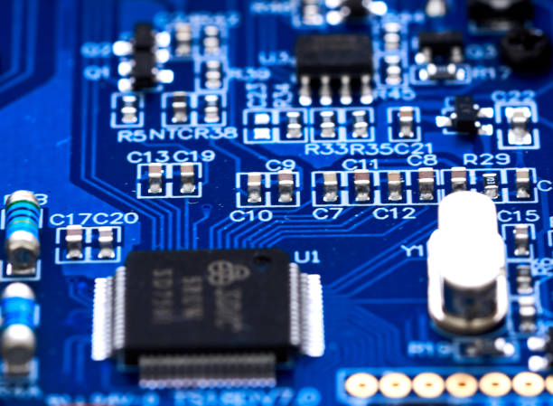
One effective way to reduce schematic errors is to introduce Schematic Simulation into the PCB development workflow.
Traditional schematic checking often relies on manually reviewing symbols, nets, and component connections. Although electrical rule checking can identify certain problems, it may not fully verify whether the circuit behaves as intended.
Schematic simulation provides another level of verification. By applying appropriate input signals and observing the resulting output waveforms or node voltages, engineers can evaluate whether the circuit operates according to the expected design behavior.
This approach can help identify connection problems much earlier in the development process.
For complex projects, combining simulation with professional PCB Design Layout practices can create a more reliable design workflow from schematic development through physical board layout.
How Schematic Simulation Works
A typical schematic simulation process can be divided into three main stages:
1. Create the Schematic
The first step is to create the electrical schematic based on the intended circuit architecture.
The schematic should include all required components, signal connections, power rails, interfaces, and functional blocks. Engineers should also define appropriate component values and electrical parameters.
For example, a typical test circuit may contain:
- Voltage regulators
- Operational amplifiers
- Signal-conditioning circuits
- Power-management components
- Analog and digital interfaces
- Control signals
- Input and output connections
At this stage, clear net naming and consistent schematic organization are essential.
2. Create the Testbench
After the schematic has been completed, a simulation testbench can be created.
The testbench provides appropriate excitation signals to the required input nodes. Engineers can then define the circuit conditions under which the design will be evaluated.
For example, a voltage-regulator circuit may require an input voltage, load condition, enable signal, and other operating parameters.
The testbench allows engineers to reproduce expected operating conditions before the physical PCB is manufactured.
3. Run the Simulation
The final step is to run the simulation and observe the behavior of important nodes.
Probes can be placed on selected nodes to measure voltage, current, or waveform characteristics. The simulation results can then be compared with the expected circuit behavior.
If the simulated output differs significantly from the expected result, engineers can investigate the schematic connections, component values, signal paths, or circuit parameters.
This makes simulation a useful method for identifying potential design problems before moving into physical PCB production.
Using Simulation to Verify Circuit Connections
One of the major advantages of schematic simulation is that engineers can observe actual circuit behavior rather than simply checking whether two nets appear visually connected.
For example, consider a power-supply signal generated by a voltage regulator.
The engineer can apply an input voltage to the regulator and monitor the output node. The resulting voltage and waveform provide direct information about whether the circuit is behaving correctly.
If the expected output is missing or unstable, engineers can investigate possible causes such as:
- Incorrect component connections
- Incorrect component values
- Missing ground connections
- Incorrect power-rail connections
- Incorrect signal polarity
- Unexpected loading conditions
- Floating nodes
This type of verification can significantly reduce the risk of carrying an incorrect schematic into the physical layout stage.
How Simulation Improves PCB Design Efficiency
Complex PCB projects often require multiple design revisions. A small schematic modification can affect component placement, routing, power distribution, and other aspects of the board.
Without early verification, an error may not be discovered until after PCB layout or even after the board has been manufactured.
Integrating simulation earlier in the workflow allows engineers to identify problems before they become expensive physical changes.
A more efficient workflow can therefore be structured as:
Schematic Design → Schematic Verification → Simulation → PCB Layout → Design Verification → Manufacturing → Assembly → Testing
This approach reduces unnecessary design iterations and helps engineering teams focus their time on actual design optimization rather than repetitive troubleshooting.
For projects that require both fabrication and assembly, integrating PCB design with PCB Assembly capabilities can further streamline the transition from engineering prototype to finished electronic product.
Investigating Design Changes Through Simulation
Schematic simulation is not only useful for detecting errors. It can also be used to investigate design changes.
Engineers can modify excitation signals, component values, operating conditions, or other circuit parameters and immediately evaluate the resulting behavior.
For example, an engineer may want to determine how changing a resistor or capacitor affects:
- Output voltage
- Signal response
- Operating frequency
- Rise and fall time
- Power consumption
- Stability
- Load response
Instead of manufacturing multiple PCB versions to evaluate different configurations, simulation can provide an early indication of how the circuit is likely to behave.
This makes it particularly valuable during prototype development and circuit optimization.
Combining Simulation With the PCB Manufacturing Process
Simulation cannot replace physical verification, but it can reduce the number of problems that reach the manufacturing stage.
Once the schematic and layout have been verified, the design can proceed to fabrication. At this stage, engineers should also verify manufacturing requirements such as layer structure, trace width, spacing, via design, component footprints, solder mask, and other production parameters.
A structured design workflow helps ensure that electrical verification and manufacturing verification are both performed before production.
For prototype projects, integrating schematic verification with Rapid PCBA Prototyping can further shorten the development cycle by allowing engineers to move efficiently from a validated design to physical prototype testing.
Simulation Is Not a Replacement for Physical Testing
Although simulation can identify many schematic and circuit-level problems, it should not be considered a replacement for physical PCB testing.
Real-world PCB performance can be affected by factors that may not be fully represented in a schematic simulation, including:
- PCB material characteristics
- Parasitic capacitance and inductance
- Manufacturing tolerances
- Component tolerances
- Thermal conditions
- Electromagnetic interference
- Assembly quality
- Mechanical constraints
- Actual load conditions
Therefore, simulation should be considered an additional verification layer within the overall engineering process.
A robust development workflow combines schematic review, simulation, PCB layout verification, manufacturing inspection, assembly inspection, and functional testing.
Best Practices for Reducing PCB Design Errors
To improve design quality and engineering efficiency, PCB designers should consider the following practices:
Use Consistent Naming Conventions
Define clear and consistent rules for net names, component references, power rails, and signal identifiers. Avoid unnecessary differences caused by capitalization, underscores, or spelling variations.
Verify Critical Connections
Pay particular attention to power, ground, clock, reset, high-speed, and safety-critical signals.
Simulate Important Circuits
Use simulation to verify critical analog, power, and mixed-signal circuits before proceeding to physical PCB production.
Perform Automated Checks
Use electrical rule checking, design rule checking, netlist comparison, and other automated verification tools wherever possible.
Review Design Changes Systematically
After modifying the schematic, verify whether the change affects component values, footprints, signal connections, PCB layout, or manufacturing requirements.
Validate the Physical Prototype
After fabrication and assembly, perform electrical and functional testing to confirm that the physical board meets the original design requirements.
Conclusion
PCB design becomes increasingly challenging as circuit complexity, component density, and signal count increase. Manually checking thousands of connections is inefficient and can still leave room for human error.
Introducing Schematic Simulation into the design workflow provides engineers with an additional method for verifying circuit connections and evaluating expected circuit behavior before manufacturing.
By combining simulation, automated verification, structured PCB Design Layout, manufacturing checks, and physical testing, engineering teams can reduce design errors, minimize unnecessary revisions, shorten development cycles, and improve overall PCB quality.
The goal is not simply to design a PCB faster. A more effective approach is to build a verification process that detects problems as early as possible—before they become expensive manufacturing or assembly issues.