




PCB Grounding and Power Routing: Design Guide
PCB grounding and power routing determine how current reaches every component and how return current finds its way back to the source. A board can have the right schematic and still fail if the power and ground nets are routed carelessly. Modern products need more than a few vias connected to a power or ground area.
Power delivery affects voltage drop, noise, thermal balance, signal integrity, and electromagnetic interference. Grounding affects return paths, shielding, and the stability of every circuit on the board.
This guide explains practical PCB design rules for grounding and voltage routing, including two-layer boards, power and ground planes, and component thermal connections.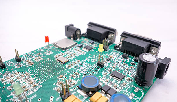
Why Power and Ground Routing Need Care
In older, slower designs, a few vias to the power plane were usually enough. The board operated at low frequency, currents were small, and noise did not disturb nearby circuits.
Modern electronics use faster signals, tighter timing, and lower voltages. Power delivery networks now affect processor stability, analog accuracy, wireless performance, and reliability. A poor power or ground network can create failures that are difficult to reproduce and debug.
Every component must receive clean power at the correct voltage. Every signal must have an uninterrupted return path. The layout engineer must manage the power distribution network as part of the overall board design.
Grounding and voltage routing therefore require planning, not just automatic routing.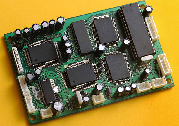
Grounding and Power Routing on Two-Layer Boards
Although dense multilayer boards are used in advanced products, low-cost two-layer PCBs remain common for toys, simple controls, sensors, and consumer products. These boards reduce manufacturing time and cost, but their power network still needs careful design.
With only two layers, there is no internal plane for power or ground. Power must be routed as traces on the surface, while the signal and return paths share the available copper.
In most applications, the designer should use the minimum trace width that can be manufactured reliably at low cost. The required width increases as the current increases, so the power trace width must be sized for the maximum current in each branch.
When routing a two-layer board, signal and power traces should be placed on the top layer when possible, with the bottom layer used as the return path. A solid bottom ground area is the simplest and most reliable return path for signals.
Some signal routing may have to use the bottom layer. When it does, the designer should avoid cutting the ground return path and should keep a clear copper path beside each signal.
Plan Power Routing Before Signals
A bottom ground plane helps control noise and signal integrity, but it also consumes routing space. Power traces on the top layer therefore need careful planning so that power reaches all parts of the board evenly.
The layout should begin by identifying every power net and its current requirement. The designer should then route the main power distribution before placing the final signal traces.
If power is routed last, the traces may be forced through narrow gaps and around obstacles, causing excessive resistance and voltage drop. Power should flow through short, direct paths with enough copper for the expected load.
Decoupling capacitors should be placed close to their loads and connected so that they can supply current during fast switching events.
Trace Width and Current Capacity
PCB trace width is directly related to current capacity. A narrow trace has more resistance, generates more heat, and can act as a fuse when current is too high.
The designer should calculate the required width from the trace current, copper weight, ambient temperature, and allowable temperature rise. Many PCB calculators apply IPC-2221 rules for internal and external traces.
Long traces may need to be wider than short traces because resistance increases with length. Power branches should be checked for the worst-case load combination, not only the average current.
Trace resistance also creates a voltage difference between components. Low-voltage digital circuits may need thicker copper or multiple parallel traces to keep the voltage at every IC within specification.
Thermal Balance for SMT Pins
When an SMT pin is connected to a large ground or power area, the metal conducts heat away from the joint during soldering. A pin attached to a large plane heats more slowly than a pin attached to a narrow trace.
This thermal imbalance is especially visible in small two-terminal components. One pad may reach soldering temperature quickly while the other pad is still cold because it is connected to a large copper area.
If the solder on one pad melts before the other, the component can be pulled into a standing position called a tombstone. The result is an open connection and a failed board.
To avoid the problem, the trace connecting a small SMT pad to a power or ground plane should be wide enough for the current but narrow enough to limit heat loss. Thermal relief connections balance current capacity with soldering performance.
Connecting the pad with several short traces or spokes provides the copper needed for current while reducing the direct heat path from the pad to the large plane.
Through-Hole Pins and Thermal Relief
Through-hole component pins connect to power and ground traces in the same way as other routed signals. The trace should enter the pad directly so that the connection is clear and reliable.
When the trace is wider than the pad or when the pad is inside a solid copper plane, a thermal relief should be used. The relief allows enough metal to carry current while reducing the amount of heat removed from the pad during soldering.
PCB design tools let the engineer control spoke width and spacing for the thermal pad. This makes it possible to supply enough copper for the electrical requirement without creating a soldering problem.
The relief design should also be reviewed for high-current pins. If the spokes are too narrow, the connection can overheat even though the plane can carry much more current.
Power and Ground Planes in Multilayer Boards
Multilayer boards often include dedicated power and ground layers in the stackup. Planes provide a simple way to connect components without wide surface traces and make routing easier for dense designs.
A ground plane also gives every signal a nearby return path. Return current can flow directly beneath the signal trace instead of taking a long route through the circuit.
Ground planes help reduce loop area and electromagnetic interference. They also provide shielding between active signal layers and reduce crosstalk between adjacent routing layers.
Digital circuits create switching noise on the ground net. A large plane has lower impedance than a thin ground trace, so the noise causes a smaller voltage disturbance on other circuits.
A ground plane can also spread heat from high-power components. When a hot part is connected to the plane with vias, heat moves across the board and lowers the local temperature.
Return Paths and Signal Integrity
Every signal needs a return path from its destination back to its source. If the return current cannot flow under the trace, it must find another route through the board.
An indirect return path creates a large loop. The loop acts as an antenna and produces noise that can disturb other circuits. Signals may also lose timing or pick up crosstalk when their return path is broken.
A solid ground plane below the signal layers provides a low-impedance return path. It is important not to cut the plane with long slots, because a slot can force return current around the opening and create a large loop.
When a trace changes layers, the return current must also change layers. Ground vias should be placed beside the signal via so the return current has a short vertical path.
At high frequency, return current flows directly under the signal trace. A plane that is continuous under the routing area gives the best signal integrity.
Ground Planes and Shielding
A ground plane helps shield sensitive circuits from external electromagnetic interference. It also prevents noise from one section of the board from radiating into another section.
Placing a ground layer between two active signal layers reduces lateral coupling or crosstalk. The ground plane absorbs the electric field between the layers and keeps the signals independent.
Shielding is most important when the board contains radios, analog sensors, power switching circuits, and high-speed digital logic in the same assembly.
The ground plane must be connected to the system ground and chassis where required. A floating shield plane can become an antenna instead of providing protection.
Split Planes and Mixed-Signal Grounding
Power and ground planes are not always continuous. Some boards need separate areas for different voltages or for analog and digital ground connections.
Split planes can be useful for power isolation, but they must be managed carefully. A split in the ground plane can break a signal return path and create severe noise.
Signal traces should not cross a split plane unless the return path is handled correctly. When a trace must cross, a bridge or stitching capacitor may be needed to provide a return path.
For mixed-signal boards, the analog and digital ground connection should be made at a single point chosen by the designer. The ground areas should be connected so that digital current does not flow through sensitive analog circuitry.
Modern PCB tools can help analyze plane splits and return paths, but the engineer must still understand the circuit currents and noise sources.
Disadvantages of Adding Planes
Dedicated power and ground planes increase the number of layers and the cost of the PCB. A simple two-layer product may not need them, while a high-performance product may require four, six, or more layers.
Planes also require careful management of analog, digital, and isolated regions. The engineer must decide where the planes should be split and how return currents will flow.
If a split plane is used for multiple voltages, the current distribution must be reviewed. A low-current voltage area may still need a complete return reference for its signals.
These issues are solved during PCB design, not by relying on the fabrication process. The board manufacturer can build the stackup, but it cannot repair an incorrect return path.
PDN Analysis and Simulation
Power delivery network analysis checks the impedance between the power and ground planes. At high speed, the target impedance should be low over a wide frequency range so that switching currents do not create large voltage changes.
Decoupling capacitors are placed between power and ground to supply current during transient events. Capacitor selection, placement, and connection determine how effective the PDN will be.
Signal integrity simulation can also show the effect of ground return paths, vias, and layer transitions. Running a simulation before fabrication reduces the chance of an expensive redesign.
For advanced products, an experienced PCB design and layout team should review the stackup, plane assignment, and decoupling strategy.
Working With a PCB Manufacturing Partner
The design team should share the stackup and plane requirements with the PCB manufacturing partner before release. Copper weight, layer spacing, and via size affect both power delivery and signal performance.
The manufacturer should verify that trace width and spacing meet the minimum requirements for the selected copper weight. A design that is electrically correct but cannot be manufactured should be corrected during DFM review.
Ground and power routing affects the whole PCB assembly process as well. Thermal reliefs and pad connections must be suitable for the soldering method used by the assembly partner.
When boards are assembled, the factory should support PCBA testing that verifies voltage, ground continuity, and signal behavior. A board with correct routing should pass these checks at the first attempt.
Continuous process improvement and quality management ensure that the fabricated board matches the designed power and ground network for every production lot.


