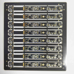
PCB Panelisation and Breakaway Design for Assembly
The panel is what the assembly line actually handles. Boards are built in groups because a machine that places components efficiently needs a surface with enough area, and because handling one small board at a time wastes more time in transport than it saves in material. Panelisation is the design of that group.
It looks like a fabrication detail and it behaves like a manufacturing constraint. The spacing between the boards, the way they are held during printing and reflow, and the way they are separated afterwards all determine whether the assembly process runs cleanly or produces damage on every unit.
Why the Panel Matters to Assembly
A panel gives the machine a larger working area, a rigid edge for the conveyor and a repeatable reference for placement. It also allows the stencil, the printer and the oven to be set up once for a group of boards rather than once for each.
The constraints come from the machines: the maximum and minimum panel size the conveyor accepts, the width of the rails, the space needed for fiducials and the clearance the placement head needs around the panel edge. Those numbers are the starting point for the layout of the group.
Tooling Strips and Board Spacing
A tooling strip is the border of the panel that the conveyor grips and the machine uses for reference. It has to be wide enough for the rail and for the fiducials, and it must not carry components, because it will be discarded after depaneling.
The spacing between adjacent boards is set by the depaneling method and by the placement machine. Routing needs a gap for the cutter, while a v-cut needs a straight line and a defined web thickness. Too small a gap leaves burrs or damages the edge, and too large a gap wastes material.

Tab Routing and V-Cut Compared
Tab routing separates the boards with a milling cutter that follows the outline except at a few tabs, which are then broken or cut. It allows curved outlines and mixed board shapes, and it leaves a clean edge where the cutter has passed.
A v-cut scores a straight groove along the panel on both sides and the board is snapped afterwards. It is fast and cheap, and it requires a straight line the whole way across the panel, which rules it out for shapes with cut outs or curved edges.
Breakaway Tab Design
The breakaway tab is the small piece of material that connects the board to the panel until the last operation. Its width and the number of tabs decide how much force is needed to separate the board and how much of that force reaches the components near the edge.
Perforations, or a row of small holes across the tab, reduce the force and leave a cleaner edge in exchange for a slightly weaker panel. The choice depends on the mass of the assembly and on how close the components are to the separation line.

Component Clearance Around the Break Line
Component clearance is a layout rule with a mechanical origin. A part placed within a few millimetres of a tab or a v-cut will see the bending and the vibration of separation, and the damage it suffers may not appear until the product is in use.
The rule is usually expressed as a keep out band along every edge that will be depanelled, and its width follows from the panel thickness and the separation method. Tall parts, ceramic capacitors and crystals are the ones most likely to suffer, and they deserve the largest margin.
Panel Stiffness and Depaneling Stress
A large panel of thin boards flexes during handling and during reflow, and the flexure stresses the solder joints of the largest components. The panel design can add stiffness through the tooling strips and through the arrangement of the boards within the panel.
Where the boards are thin, or where the assembly carries heavy parts, the panel may need additional rails across the middle. Those rails have to be placed where they do not obstruct the stencil or the placement head, which is another constraint that belongs in the layout rather than in a later discussion.
Fiducials, Bad Marks and Machine References
Every panel needs fiducials that the placement machine can find, and they should be placed on the tooling strip rather than on the boards, so that they survive until the last operation. A local fiducial next to a fine pitch device is also worth adding where the placement accuracy is marginal.
Bad marks are the panel level equivalent of a reject tag. A panel that is found to be defective at printing can be marked so that the machine skips the placement on that board, which saves components and prevents a known bad unit from being built.
Panel Size and the Assembly Line
The panel size has to suit the smallest machine in the line, not the largest. A printer, a placement machine and an oven each have their own limits, and the panel has to pass through all of them, including any buffer or transfer unit.
The weight matters as well, since a heavy panel is more difficult to clamp and more likely to distort in the oven. Where the design demands a large board, the panel may have to be split into two groups that are assembled separately, which changes the cost model and therefore belongs in the quotation discussion rather than being discovered at the printer.
Documentation and Handover
The panel drawing is part of the manufacturing package. It shows the board arrangement, the spacing, the tab positions, the fiducials and the tooling strips, and it is the document the assembly house works from when it sets up the line.
Because the panel affects cost, yield and the assembly process at the same time, it is worth reviewing with the assembly house before the data is released. That conversation is the same one that belongs to the wider design release review, and it is much cheaper than a change after the first panels have been produced.
Depaneling Method and Edge Quality
The separation method decides what the board edge looks like when it arrives at the next operation. A routed edge is clean and slightly rounded, a v-cut edge shows a small ridge where the score was placed, and a broken tab leaves a small burr that may have to be removed before the board will fit into its enclosure.
Burrs matter more than they appear to. A burr in a connector opening can prevent a mating part from seating, and a burr near a screw hole changes the mechanical interface. Where the product has a tight mechanical fit, the separation method should be chosen with the finished edge in mind, and the requirement belongs with the other mechanical notes in the design release checklist and the fabrication notes that accompany the panel drawing.
FAQ
Should the panel be designed by the fabricator? It can be, but the assembly constraints are the ones that matter most. The panel should be agreed with the assembly house even when the fabricator draws it.
How wide should the spacing between boards be? Enough for the depaneling method and for the cutter, typically a few millimetres for routing. The exact figure comes from the process rather than from a general rule.
Can a very small board be assembled without a panel? It can, but handling becomes difficult and the placement machine may not be able to clamp it. Grouping small boards in a panel is usually the practical answer.