PCB Panelization and SMT Assembly Efficiency
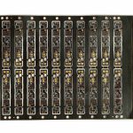
Data packages are usually reviewed for the bill of materials, the coordinates and the delivery date, and the panel drawing receives much less attention than it deserves. How a small board is repeated across a production panel decides how well the placement machine can locate it, how stable it is through the oven, how cleanly it separates afterwards and how much stress the components near the edge have to survive.
PCB panelization is therefore a manufacturing decision that happens to be made in the design file. A layout that is correct as a circuit can be awkward to build, and the awkwardness usually appears as a yield loss rather than as an error, which makes it easy to miss until the quantity is large enough to matter.
Why Boards Are Combined Into a Panel
Placement equipment works best with a panel of a convenient size rather than with a single small board. The panel gives the machine something to clamp and transport, allows the stencil to print several boards in one stroke, and lets the oven and the inspection equipment process a batch at a consistent speed.
The gain is not only throughput. A small board handled individually is difficult to locate precisely and easy to damage during transport, while the same board repeated on a panel is held flat and positioned by the tooling that the machine understands. Panelization is what makes a small design behave, on the line, like a larger and more stable one.
The trade-off is that the panel has to be designed. It needs an edge for the machine, features for alignment, a separation method that suits the board outline, and enough clearance around each board that the operation of separating it does not disturb what has been assembled.
The Process Edge and Tooling Features
The process edge is the strip of material outside the board outline that the machine grips and that carries the tooling features. Its width has to be sufficient for the conveyor and the clamps, and it should not be the place where a designer places an edge connector or a component that must remain undisturbed.
Alignment features belong to the same strip: tooling holes for the machine and fiducials for the placement and inspection systems. Fiducials need clear space around them, with no copper or silkscreen nearby that could be mistaken for the mark, and they need to be positioned so that the whole panel can be corrected from them by translation and rotation.
A board with a very small outline, or an irregular one, generally needs the panel to provide both the handling edge and the mechanical stability that the board itself lacks. Designing that in advance costs a little board area; discovering the need after the bare boards have been produced costs a new order.

Separation: V-Cut, Tabs and Routing
There are three common ways to separate the boards, and each suits a different outline.
A V-cut scores both faces of the panel along a straight line. It is fast, it leaves a clean edge, and it suits rectangular boards laid out in a regular grid. It requires a straight separation line, a sufficient board thickness to leave a defined web, and enough distance between that line and any component or solder joint, because the separating operation applies a bending moment along the whole length of the score.
Break-away tabs with small perforations suit outlines that cannot be scored, including boards with curves or with features on every edge. The penalty is a rougher edge, which may need cleaning if the board is visible in the finished product or if the edge is a mating surface.
Routed separation, whether the boards are separated with a router or held on a frame and cut later, gives the greatest freedom and the cleanest edge, at the cost of more machine time and often a fixture for the operation. For a small batch of a design that will be reordered, that cost is frequently worth paying once.
Component Clearance and the Stress of Separation
The distance between the separation line and the nearest component is the detail that causes the most trouble later. Capacitors, connectors, crystals, QFN and BGA devices close to a score line or a perforation are subjected to mechanical stress at the moment the panel is flexed or the tab is broken.
The consequence is not always an immediate failure. A joint can be cracked without losing continuity, a component can shift slightly, or the board edge can be damaged in a way that only shows up when the unit is fitted into its enclosure. On products that will be installed in equipment subject to vibration, the effect of that stress accumulates.
Tall components near the edge present a second problem, because they obstruct the tooling of the separating equipment and may be struck during the operation. The rule that works is to keep the region along the separation line clear, and to treat the width of that region as a specification rather than as a preference.
Panel Size, Orientation and the Rest of the Line
The panel has to fit the equipment that will process it, and it has to travel through the oven in a way that heats it evenly. Where the panel is long and narrow, the thermal mass along the length is uneven and one end of a board may see a different profile from the other. Where the arrangement is asymmetric, the panel may distort towards the side with more copper or more mass.
Orientation through reflow is a related decision. Whether the long or the short edge leads into the oven, and how the heavier components are distributed across the panel, both affect the stability of the joints that are formed.
Boards that carry inserted devices, connectors or heavy parts add a further constraint: the panel has to survive the handling that follows the surface mount stage, and the separation method has to be compatible with it. A panel that is ideal for placement can still be poor for the insertion and test steps.
Reviewing the Data Before the Order
Most of the difficulty is removed by a short review at the enquiry stage: whether the board is small enough to need a panel, whether the handling edge is wide enough, whether the alignment features are complete and correctly spaced, whether components sit close to the separation line, and whether the finished board has to fit into an enclosure that constrains the edge.
Where the answers are unclear, the question is better asked before the bare boards are made than after. The relevant stages are SMT assembly, mixed technology assembly where the board also carries inserted parts, and the controls that keep the process repeatable under quality management.
FAQ
Does a small batch need a panel? Very often, yes, because the panel is what lets the machine locate and transport a small board reliably. The quantity affects the cost of the panel, not the need for it.
Which separation method is best? It depends on the outline. A regular rectangle suits a V-cut, an irregular shape suits tabs or routing, and the choice should follow the edge quality the finished product requires.
What is the most common panelization mistake? Placing components too close to the separation line, which converts a routine operation into a source of cracked joints and shifted parts.