PCB Routing Strategy: Corners, Differential Pairs and Serpentines
Routing is where the theory of high-speed design either survives or dies. A stackup can be textbook-clean and the schematic can be perfect, but if the traces are laid down carelessly the board will still miss its timing window or fail EMC. A workable PCB routing strategy comes down to three decisions that repeat thousands of times on every board: how a trace turns a corner, how a differential pair is routed, and how extra length is added when two paths have to match.
What a Corner Actually Does
The standard advice is to avoid right-angle routing, and the physics behind that advice is smaller than most engineers expect. A right angle widens the trace locally, which lowers the impedance at that point and creates a small reflection. On a 4 mil, 50 ohm trace in typical FR-4 the equivalent capacitance of one corner works out below 0.02 pF, and the resulting impedance disturbance lasts tens of picoseconds. On a time-domain reflectometer it is difficult to see at all.
That is not a reason to lay corners casually. The real cost of a right angle is consistency: the impedance change is real even if it is small, the acute corner traps etchant during fabrication, and at the tip of the corner the copper is thinner than on a straight run, which matters when the trace carries current or has to survive thermal cycling.
Where Corners Start to Matter
Corner geometry becomes a genuine design variable as the frequency rises. Above roughly 10 GHz the discontinuity is a measurable fraction of the wavelength, and in RF work an unmatched corner radiates. The practical compromise used on most boards is a pair of 45-degree segments instead of a single 90-degree turn, which halves the local impedance change and removes the acute angle that traps etchant. Curved, arc-based routing is better still and costs nothing extra at the design stage.
What should worry an engineer more than the corner is the stub. A short unterminated branch hanging off a net is a resonant structure, and at multi-gigabit rates a 2 mm stub has a quarter-wave resonance inside the band of interest. Back-drilling, blind vias and via-in-pad construction all exist to remove stubs rather than corners.
Differential Pair Routing
Differential signalling is preferred for three reasons: common-mode noise picked up equally by both lines is cancelled at the receiver; the opposing currents partially cancel the radiated field; and the decision threshold is defined by the crossing point of the pair, which is far less sensitive to supply and temperature variation than an absolute threshold.
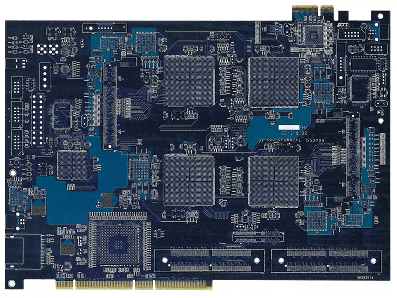
To keep those advantages, the pair has to stay symmetric. Route both traces on the same layer for as long as possible, keep the intra-pair spacing constant, and match the pair to itself rather than to the whole bus: skew within a pair should stay under about 0.15 mm, while group-to-group matching is a separate budget. Where a via is unavoidable, place one on each trace of the pair side by side so the discontinuity is common mode. Right angle routing and differential traces covers the corner geometry specific to pairs, which is more forgiving than single-ended intuition suggests.
Serpentine Routing for Length Matching
serpentine routing adds electrical length without adding distance in the direction of travel, and it is the standard way to match a clock to its data group or one lane of a bus to another. The mistake is to treat it as a pure delay element. Adjacent meander segments couple to each other, so a tight serpentine with a small pitch behaves like a coupled line and changes both the impedance and the effective delay.
The rules that keep it predictable are straightforward. Use the largest amplitude the available space allows rather than the smallest pitch, keep the gap between adjacent meander segments at least four times the trace width, and keep the meander away from the ends of the net where reflections accumulate. A serpentine placed close to a switching node or a clock will pick up noise even if the length calculation is perfect. Serpentine routing for length matching sets out the geometry in more detail.
Spacing, Crosstalk and the 3W Rule
Crosstalk falls with the square of the separation between traces, which is why the 3W rule has survived so long: keep the centre-to-centre spacing at three times the trace width and the coupling is usually acceptable for ordinary signals. On long parallel runs at high edge rates it is not enough, and the coupling gets worse when the traces are not referenced to a plane or when the parallel run is longer than about 10 mm. The crosstalk and 3W rule is a starting point, not a guarantee.
Guard traces help, but only if they are stitched to ground at both ends and at regular intervals. A floating guard trace is worse than no guard at all, because it couples noise from one line to the next.
Return Paths and Layer Changes
Every signal has a return current, and at high frequency the return flows in the plane directly beneath the trace. When a trace changes layers, the return has to change planes too, which means a ground stitching via must sit within a few millimetres of the signal via. Without it the return takes a detour around the plane, the loop area grows, and the trace radiates.
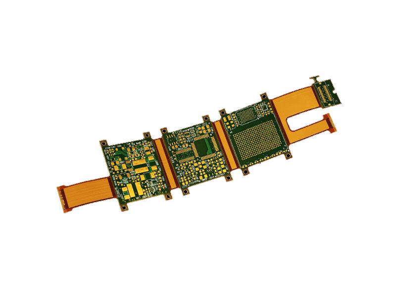
Keep the number of layer changes small on any critical net and keep the plane structure simple. A board with three different ground regions and two power islands forces the return current to negotiate a maze, and the consequences appear as crosstalk and common-mode radiation rather than as a clean failure. Where a split is unavoidable, add stitching capacitors close to the crossing point and accept that they only work below the frequency where their equivalent series inductance takes over.
Never route a high-speed signal across a plane split. If a supply island forces a split, route the signal around it or add stitching capacitors across the gap, and remember that the capacitor only helps below the frequency where its ESL dominates.
Reviewing a Route Before Release
A route review is faster when it is a checklist rather than a discussion. Confirm that every controlled-impedance net has a solid reference on the layer below it; that every layer change has a nearby ground via; that pairs are symmetric and within skew budget; that serpentines are spaced widely enough; that no switching node runs parallel to a sensitive line; and that test access exists for the nets that will need it. Fixing a routing problem on screen costs minutes, and fixing it on a fabricated panel costs a revision.
FAQ
Are right-angle traces really forbidden? No. The electrical penalty at ordinary digital frequencies is small. The reasons to use 45-degree or curved corners are fabrication consistency and impedance continuity, and both are easy to satisfy once the habit is in place.
How tight should a serpentine be? As loose as the space allows. Keep the pitch large, the segment gap at least four trace widths, and the meander away from the ends of the net. Tight serpentines couple to themselves and stop behaving like simple delay.
Do differential pairs need to be matched to other pairs? Only if the interface requires it. Intra-pair skew is the critical parameter and should stay under about 0.15 mm. Inter-pair matching matters for parallel buses where the receiver samples all lanes together.