Component Placement Sequence Optimisation for SMT Assembly
Component placement sequence is the order in which a machine places parts on a board, and it is one of the few variables in surface mount assembly that can be changed without touching the design or the process. A well ordered program reduces the distance the head travels, shortens the time each board spends in the machine and lowers the chance of a placement error.
Why Placement Sequence Matters
The placement sequence determines how far the head moves between picks and places, so it drives the cycle time of the machine directly. It also decides when each part is placed relative to the others, which matters when a component is delicate, tall or easily disturbed by a later placement. A sequence also fixes the moment at which the paste under each pad is exposed to air, and on a long program the parts placed first can sit on printed paste for several minutes longer than the parts placed last.
On a line that runs several products the sequence has a second effect, because it changes how much of the feeder setup can be shared. A sequence built around the feeders that are already loaded is usually faster to change over than one optimised in isolation for a single board.
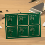
<img src="https://www.gopcba.com/wp-content/uploads/2025/08/31.png" alt="Pick and place machine placing components in an optimised sequence on a PCB” />
How a Placement Program Is Built
The program starts from the CAD placement data, the bill of materials and the machine library. Each part is matched to a package definition, a nozzle and a feeder position before any ordering is attempted, because the sequence depends on where the parts will be presented.
Most machines then optimise the order automatically, using the head configuration and the feeder positions as constraints. The result is a first draft that is normally five to twenty percent faster than a program written by hand, and it is only the starting point for the engineering decisions that follow.
Feeder Arrangement and Its Influence
The feeder arrangement is the foundation of the whole program. Feeders should be grouped by tape width and by the nozzle that picks them, and the parts used most often should sit closest to the placement area so the head spends less time travelling to the far end of the bank. Splitting a tall stack of identical parts across two feeders reduces the number of refills in a shift, but it also costs two slots, so the decision depends on the batch size and on how easily the operator can reach the machine.
Heavy reels belong low and near the centre of the machine, where the trolley is most stable, and tall parts should not block the path of the head. Where two products share a line, the feeders that both use should be placed in the positions that both programs prefer.

Nozzle Selection and Component Handling
The nozzle decides how reliably a part is picked and how accurately it is placed. A nozzle that is too small grips the edge of a package instead of its body, and one that is too large can lift two parts from the tape at once or leave a vacuum leak that drops the component during travel.
Fragile parts such as thin packages and large connectors are often placed at a lower speed, and that exception is written into the sequence rather than left to the operator. Nozzle wear is a slow effect, so the vacuum level and the pick height are checked at planned intervals. The pick height is set from the tape pocket rather than from the component body, and a height that is set too deep pushes the parts down into the pocket so that they are picked at an angle or not at all.
Board Support and Fiducial Strategy
Support underneath the board keeps the surface flat while the head presses down. Without it the board flexes, the paste is disturbed and the measured placement height varies, which shows up later as tombstoning or as a part that settles on its side.
Fiducials give the machine a reference, and they should be read at the start of the program and again after any board transfer that could shift the panel. Local fiducials are used for fine pitch parts where the global reference is not accurate enough across the whole panel.
Cycle Time, Throughput and Line Balance
Cycle time is the total time the machine needs for one board, and it is the sum of the pick and place movements, the vision alignments and the transfers. Reducing it is not the same as making the machine faster, because the slowest placement in a sequence can set the rate for the whole board. A single part that needs vision alignment, a slow speed setting or a second pick attempt can add more time than a long run of simple chip placements, so the exceptions are where the effort belongs.
Line balance matters as much as the individual program. If one machine is loaded with more work than the others, the line waits for it, and the spare capacity on the neighbouring machines is wasted no matter how efficient their own sequences are. The wider arrangement of these steps is covered in the guide to production process flow.
Placement Order for Thermal and Mechanical Reasons
Placement order also has a physical side. Placing a large part before a small one can make the small part harder to reach, and placing a heavy part late can disturb paste that has already been printed for the neighbouring pads.
Where several parts share a thermal path, the larger thermal mass is usually placed first, so that the smaller parts around it are not displaced when the package settles. Connectors and shields that sit over other components are placed last, after the parts they cover have been verified.
Qualification and Verification of a New Program
A new program is qualified with a first article inspection that covers placement position, rotation and the presence of every part. The measured offsets are compared with the tolerance allowed by component tolerance, and any systematic error is corrected in the program rather than left to the operator.
The program should then run for a full batch before it is released, because some faults appear only when the machine has warmed up or when a feeder has been refilled. The results are recorded with the program version so that a later change can be traced back to the board it affected.
Common Faults and Their Causes
Missing parts usually point to a feeder or a nozzle rather than to the sequence, while parts placed at an angle point to vision or to a package definition that does not match the real component. Tombstoning has more to do with the print and the reflow profile than with the order of placement.
A slow but correct program is the least visible fault, because nothing fails and the line simply produces fewer boards than it could. Comparing the measured cycle time with the calculated figure shows whether the sequence is doing the work it was meant to do, and the same comparison highlights the feeder positions that cost the most time. Machine logs help here, because the time recorded for each placement shows whether the loss comes from travel, from a vision step or from a feeder that fails to advance cleanly. The data turns a general complaint about speed into a specific position on the trolley.
FAQ
Does optimising the placement sequence change the quality of the joints? Only indirectly. The order changes how long the paste sits before reflow and how much the board is handled, so a shorter program can reduce defects, but the joint itself is formed by the print and the profile.
How often should a placement program be reviewed? Whenever the product, the feeder setup or the machine configuration changes, and after any batch that shows a placement defect that cannot be traced to a single component.
Is automatic optimisation always better than a manual sequence? It is a better starting point, but it does not know that one part is fragile or that another must be placed last, so those rules still have to be added by the engineer.