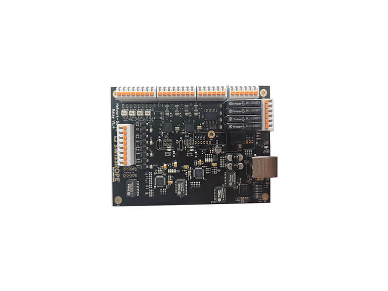
Press Fit Pin Insertion: Hole Tolerance and Insertion Force
A press fit pin forms its connection by deforming the copper in a plated hole rather than by being soldered to it. The pin is slightly larger than the hole, and pressing it in creates an interference fit that produces a gas-tight contact over a defined length of the barrel. Press fit pin insertion is a controlled mechanical event, and the hole tolerance, the barrel plating and the insertion tooling all have to be right for it to work.
How a Press Fit Connection Works
Three pin styles are in common use. A compliant pin has a hole or a slot in its body, which allows the pin to compress as it enters and spring back against the barrel wall. A solid pin relies on the elasticity of the hole and is used where the pin diameter is small. A needle-eye pin combines both, with an elongated opening that deforms predictably.
In each case the contact is made by plastic deformation of the copper and elastic recovery of the pin. The result is a mechanical and electrical joint that needs no solder, which is why the process is preferred for backplanes, for high pin counts and for assemblies that cannot be exposed to reflow temperatures.
Hole Tolerance and Interference
Hole tolerance is the most important single variable. The finished hole diameter has to sit inside a narrow band, often plus or minus 0.05 mm around the nominal, because the interference that produces the contact is the difference between the pin and the hole. Outside that band, the joint is either loose or the pin cannot be inserted without damaging the barrel.
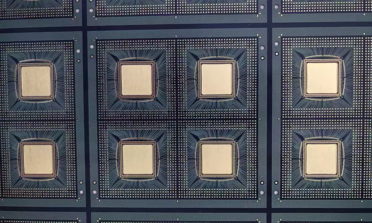
Interference is normally between 0.05 mm and 0.15 mm on the diameter for a compliant pin, and it is specified by the pin manufacturer for a given hole size. The tolerance on the hole is what the fabricator has to hold, and it is tighter than the tolerance on an ordinary component hole. Maintaining it starts with the drill registration and the drill diameter control, and ends with the plating thickness in the barrel.
Insertion Force and Its Measurement
Insertion force is the measurable result of the interference fit, and it is the practical acceptance test for the process. A force that is too low means the pin is loose and the contact may not be gas tight; a force that is too high means the pin is being forced and the barrel is at risk of damage.
The force is measured with a press that records the curve of force against displacement. A good insertion produces a smooth rise to a plateau and a slight drop as the pin seats. A jagged curve indicates a misaligned pin or a damaged hole, and the instrument should be able to reject the assembly on the shape of the curve rather than only on the peak value.
Plated Through Hole Requirements
The barrel plating has to be thick enough and ductile enough to deform without cracking. Copper thickness between 25 and 50 micrometres in the hole is common for press fit applications, and the deposit must be ductile rather than brittle, which is a property of the bath chemistry and its additives.
The hole wall quality matters as much as the thickness. A barrel with a thin spot, with a void, or with a poor bond to an inner layer will crack during insertion, and the crack may not be visible on the surface. The annular ring on the outer layers should also be large enough to support the deformation, which is a design rule rather than a process one.
Hole Wall Damage and Its Detection
Damage during insertion includes barrel cracks, inner layer separation and resin cracking around the hole. The damage is internal, so it is found by sectioning rather than by inspection. Sampling a few joints from a production lot and sectioning them after insertion is the standard verification.
Where the damage is caused by an oversized pin or an undersized hole, the section shows a barrel that has been compressed beyond its elastic limit, often with the copper pushed away from the laminate. Where the cause is a brittle deposit, the cracks run around the barrel rather than along it, which is a distinction worth recording.
Board Support and Tooling
Insertion applies a substantial axial load to the board, and the board has to be supported directly under the joint. A support plate with a hole at the pin position lets the pin pass through while supporting the laminate around it; a plate without the hole stops the pin but also takes the full force through the board.
The tooling also controls alignment. A pin that starts at an angle deforms the barrel unevenly and produces a high insertion force with a damaged result. The press should have a guide plate that holds the pin vertical until it is engaged, and the board should be constrained against lateral movement.
Reflow, Rework and Repair
Many press fit connectors are inserted after reflow, so the board has already been through its thermal cycle and the laminate is at its final dimensions. Where the connector is inserted before reflow, the insertion is done on a board that will change size slightly, and the pin-to-hole relationship changes with it.

Rework is possible but limited. A pin can be pressed out and a new one inserted, provided the hole was not damaged the first time, and the number of times a hole can be reused is defined by the pin specification. Reusing a hole beyond that number produces a loose joint, and the correct repair is usually a soldered connection or a replacement board.
Verification and Records
The record for the process should carry the pin type and part number, the nominal hole size and its measured tolerance, the plating thickness and the insertion force for each pin or for a sample. Those fields are what allow a field failure to be traced to the hole, the plating or the insertion.
For a new product the verification includes a section of an inserted joint and a pull or push-out test to the limit defined by the pin supplier. The push-out force is usually higher than the insertion force and is the better measure of the long-term contact, and the annular ring and hole size measurements taken at the same time complete the picture.
Comparing Press Fit With Soldered Connectors
A soldered connector depends on the wetting of the barrel and the pin, so it needs a solderability window and a thermal budget. A press fit connector removes both, which simplifies the assembly line, and it allows a connector to be replaced without reflow.
The trade is a tighter mechanical specification. Where a soldered joint tolerates a range of hole sizes and a moderate amount of contamination, a press fit joint tolerates neither, and the process control it demands is closer to that of a machined assembly than to that of a soldered one.
FAQ
What hole tolerance does a press fit connector need? Often plus or minus 0.05 mm on the finished hole diameter, which is tighter than a standard component hole. The exact value comes from the pin manufacturer’s specification for the pin being used.
How is insertion force used in production? As an acceptance test. The press records the force curve, and the shape of the curve shows whether the pin went in cleanly. Peak force alone is not sufficient evidence of a good joint.
Can a press fit hole be reused? Only as many times as the pin specification permits, and only if the hole was undamaged. Beyond that the joint is loose, and a soldered connection or a new board is the correct repair.