
Double Sided Assembly: Design Rules and Process Limits
A double sided assembly is reflowed twice, and the second pass is the one that causes trouble. The parts placed in the first pass are already on the board, and they have to survive a second trip through the oven without falling off or degrading.
The profile for the second pass is therefore not the same as the first, and the decision about which side to run first follows from the thermal mass and the component sensitivity.
Which Side Goes First
The side with the heavier components and the larger thermal mass is usually run first, so that the second pass can use a lower peak. The side with the fine pitch parts benefits from the cleaner first pass.
The decision also depends on the process: a board with parts on both sides needs either an adhesive or a reflow that does not disturb the underside.
Holding the Underside Parts
A chip part on the underside is held by the surface tension of its joints once the second reflow begins, and by adhesive before that. The surface tension is often sufficient for a small part, while a heavy part needs adhesive.
The adhesive is applied before the first reflow and cured during it, which is why its cure temperature has to be below the alloy melting point. Its placement is described for component bonding.
Thermal Mass of the Second Pass
By the second pass the board carries copper and components that change its thermal behaviour, so it heats differently from the bare board the first profile was developed on. The profile should be measured with the first side populated.
The difference is largest on a board with a heavy component or a large plane, and it can shift the effective soak and the time above liquidus appreciably.
Component Limits
Every component has a maximum number of reflow cycles, and a double sided assembly consumes two. A part that is limited to one cycle requires a selective soldering or an adhesive attachment for the second side.
The limit should be read from the component data rather than assumed, because it varies widely between package types.
Moisture and the Second Bake
A board that has been through one reflow has been dried by it, so the moisture risk on the second pass is lower. The parts placed in the first pass have also been baked by the process.
Where a long interval passes between the two passes, the board can reabsorb moisture and the consideration returns. The interval should be controlled.
Warpage and Support
A populated board warps differently from a bare one, and the second pass has to support it accordingly. The support positions used for the first pass may not be appropriate.
The support should be reviewed when the second side is introduced, particularly where a large component creates a local stiffening effect.
Profile Development
The second profile is developed with the first side populated and with a representative panel loading. The measurement positions should include a joint on the underside, since that is where the risk is.
The result is compared with the paste specification and with the component limits, and the profile is released for that side only.
Yield Effects
Defects on the second pass are more expensive, because the board already carries value. The defects include parts falling off, tombstoning on the underside and head in pillow on the second side.
Where those defects appear, the profile, the adhesive and the support are the items to review in that order. This is the same reasoning applied in zone verification.
Records
The records should identify the profile for each side, the adhesive used and the support arrangement. A board that is built with two profiles and no record cannot be reproduced.
They belong with the process evidence described for manufacturing processes.
Additional Considerations for This Build
Practical attention to reflow profile pays for itself here, because it decides whether the finished board behaves as the drawing intended. Where the requirement is not stated on the fabrication drawing or in the assembly notes, the shop has to assume a default, and that default is rarely the value the design was simulated with. Stating reflow profile explicitly, together with the tolerance that applies, removes the assumption and keeps the result predictable from batch to batch.
Process Control and Verification
On a design of this kind, adhesive is the item that decides how the rest of the board is arranged. Where a value sits close to a process limit, the drawing should say so, since the shop can then open the process window rather than working to a nominal figure that carries no tolerance. A stack-up that is drawn rather than described removes most of the ambiguity from a quotation, and it lets the fabricator price the board against the dielectric and copper weights that will actually be used.
Where the requirement is not written down, the shop supplies its own default, and the default is chosen for the process rather than for the design. The measurements that matter are the repeatable ones: conductor width and spacing, annular ring, finished hole size, plating thickness and surface finish are all verifiable on a coupon that travels with the panel.
Running a first article through the same checks as the production panel confirms that the two agree, and that comparison is the cheapest form of process control available at prototype stage. Keeping a sample from the panel turns a dispute into a measurement, because the same coupon can be re-examined by both parties without rebuilding the batch.
Reviewing the design before the data is released is cheaper than correcting it after the panel is in the tank, because every step downstream inherits the decision made at the front end.
Process Control and Verification
On a design of this kind, adhesive is the item that decides how the rest of the board is arranged. Where a value sits close to a process limit, the drawing should say so, since the shop can then open the process window rather than working to a nominal figure that carries no tolerance. A stack-up that is drawn rather than described removes most of the ambiguity from a quotation, and it lets the fabricator price the board against the dielectric and copper weights that will actually be used.
Where the requirement is not written down, the shop supplies its own default, and the default is chosen for the process rather than for the design.
Process Control and Verification
On a design of this kind, adhesive is the item that decides how the rest of the board is arranged. Where a value sits close to a process limit, the drawing should say so, since the shop can then open the process window rather than working to a nominal figure that carries no tolerance. A stack-up that is drawn rather than described removes most of the ambiguity from a quotation, and it lets the fabricator price the board against the dielectric and copper weights that will actually be used.
A first article check confirms that the process and the drawing agree on the points listed above, and that the coupon data supports the values used in the design.
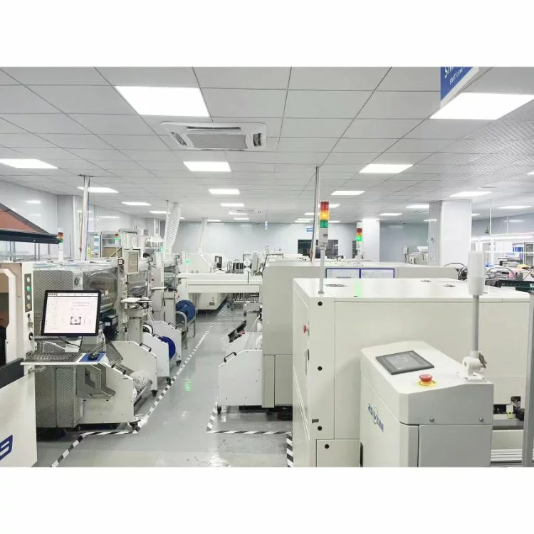
Where a measurement falls outside the expected window, the sample is retained so that the cause can be established before the balance of the batch is released.
A first article check confirms that the process and the drawing agree on the points listed above, and that the coupon data supports the values used in the design.
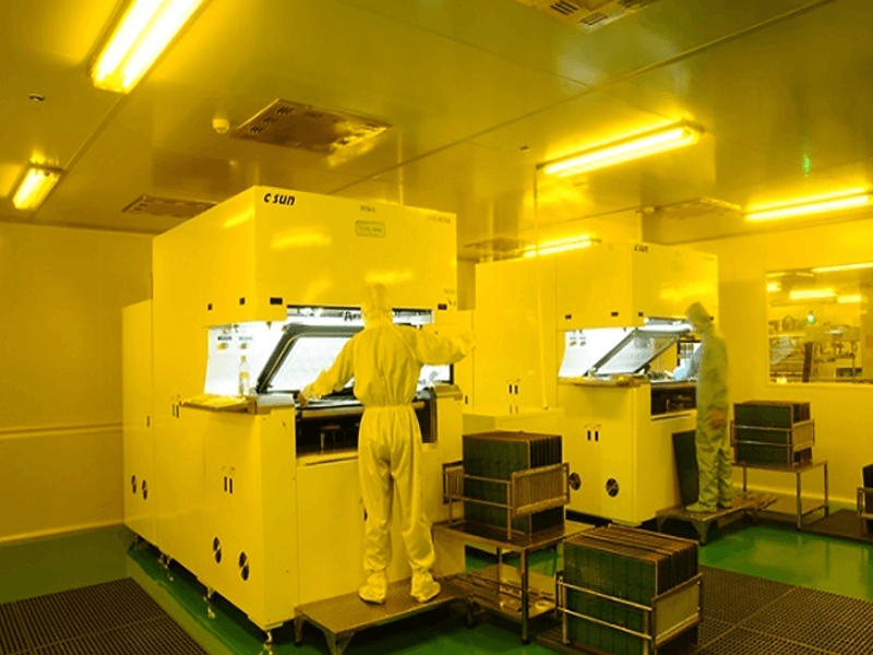
Where a measurement falls outside the expected window, the sample is retained so that the cause can be established before the balance of the batch is released.
FAQ
Does every second side need adhesive? Only where a component is heavy enough that surface tension will not hold it during the second reflow.
Can the same profile be used for both sides? Sometimes, and it should be demonstrated with a measurement on the populated board rather than assumed.
How many reflow cycles can a part take? The supplier states a maximum, and it is often two, which is why a third pass requires a different method.
What is the most common second pass defect? Components displaced or lost from the underside, followed by joint defects in the parts placed second.