Prototype PCBA: PCB Design, PCB Manufacturing & Prototype Assembly Guide
Modern electronic products are becoming increasingly compact, intelligent, and functionally complex. From the initial concept and circuit design to engineering validation and mass production, developing an electronic product requires a carefully controlled process.
One of the most important stages in this process is building a Prototype PCBA (Printed Circuit Board Assembly).
A prototype PCBA transforms a schematic and PCB layout into a physical, assembled circuit that engineers can power up, test, measure, modify, and validate before committing to larger-scale production. Instead of relying entirely on simulation or computer-based design verification, engineers can evaluate how the actual hardware behaves under realistic operating conditions.
For startups, electronics engineers, product developers, and established manufacturers, prototype assembly can reveal problems that are difficult or impossible to identify from PCB design files alone.
This article explains what a Prototype PCBA is, why prototype assembly is important, how it supports PCB Design and PCB Manufacturing, and how an effective prototyping process can reduce development risks and accelerate product commercialization.
What Is a Prototype PCBA?
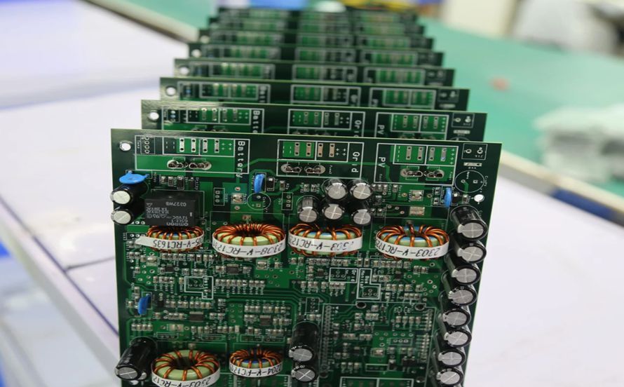
A Prototype PCBA is a printed circuit board that has been populated with electronic components for engineering evaluation and validation.
Unlike a bare PCB, which consists primarily of the fabricated circuit board itself, a PCBA includes components such as:
- Integrated circuits (ICs)
- Resistors
- Capacitors
- Diodes
- Transistors
- Connectors
- Sensors
- Microcontrollers
- Power-management components
- Electromechanical components
The purpose of a prototype PCBA is to verify whether the electronic design works as intended before the product enters full-scale manufacturing.
A typical prototype development process may include:
- Schematic design
- PCB layout
- PCB fabrication
- Component sourcing
- PCB assembly
- Initial power-up
- Functional testing
- Design verification
- Design modification
- Prototype iteration
- Pre-production validation
- Mass production
This process allows engineering teams to identify hardware problems early, when modifications are generally less expensive and less disruptive.
Why Is Prototype PCBA Important?
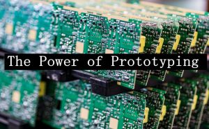
Prototype PCB assembly provides a physical representation of the electronic design.
Even when a schematic and PCB layout appear correct, real-world hardware can behave differently because of component tolerances, parasitic effects, thermal conditions, manufacturing variation, mechanical constraints, and interactions between different circuits.
A prototype therefore acts as an important bridge between PCB Design and production.
1. Identify Design Problems Early
One of the most important advantages of prototype assembly is early detection of design problems.
A prototype may reveal issues such as:
- Incorrect component placement
- Insufficient PCB clearance
- Incorrect component values
- Signal-integrity problems
- Power-supply instability
- Inadequate thermal management
- Connector interference
- Mechanical fit problems
- Unexpected EMI/EMC behavior
- Incorrect polarity or component orientation
Some problems may not become obvious during schematic review or PCB layout inspection.
For example, a component may technically fit within the PCB footprint but physically interfere with an enclosure, connector, heat sink, or neighboring component.
Building a prototype allows engineers to identify such problems before large-scale production begins.
2. Improve Functionality and Performance
A prototype PCBA enables engineers to evaluate the actual performance of the circuit.
Depending on the product, engineers may measure:
- Supply voltage
- Current consumption
- Output voltage
- Signal amplitude
- Frequency response
- Temperature
- Power efficiency
- Communication performance
- Sensor accuracy
- Battery performance
- Startup and shutdown behavior
Test results can then be compared with the original design requirements.
If the measured performance does not meet the specification, engineers can modify the circuit, component selection, layout, firmware, or mechanical design and build another prototype.
This creates a controlled engineering feedback loop.
3. Enable Rapid Design Iteration
Electronic product development is rarely a completely linear process.
Engineers frequently need to change:
- Component specifications
- PCB footprints
- Trace routing
- Power architecture
- Decoupling networks
- Connector positions
- Component placement
- Thermal structures
- Firmware
- Communication interfaces
A prototype PCBA makes it possible to verify these changes with real hardware.
Instead of waiting until mass production to discover whether a modification works, engineers can test the change on a limited number of prototype boards.
This makes prototyping particularly valuable for new and technically complex products.
4. Improve Communication and Collaboration
A physical PCBA provides something that a schematic or CAD model cannot always provide: a tangible representation of the product’s hardware.
Engineers, product managers, manufacturing teams, investors, and other stakeholders can examine the prototype and understand its physical implementation.
For example, a prototype can help teams evaluate:
- Board dimensions
- Component accessibility
- Connector locations
- Mechanical integration
- User-interface elements
- Thermal solutions
- Assembly requirements
This can make technical discussions more concrete and help different teams identify problems earlier.
5. Reduce Time to Market
Speed is important in many electronics markets.
Prototype PCBA development can shorten the overall development cycle by allowing engineers to identify and resolve problems before mass production.
An effective iteration process can be:
Design → Prototype → Test → Identify Problems → Modify → Prototype Again → Validate → Production
Although additional prototype builds require time and cost, solving engineering problems early can prevent much more expensive production delays later.
Prototype PCBA vs. Bare PCB
It is important to distinguish a prototype PCB from a prototype PCBA.
A prototype PCB is the fabricated bare circuit board without components.
A prototype PCBA is the assembled board with components installed and soldered.
For example:
| Prototype Type | Main Purpose |
|---|---|
| Prototype PCB | Verify board fabrication, dimensions, stackup, holes, routing, and basic manufacturability |
| Prototype PCBA | Verify electrical functionality, component interaction, assembly quality, thermal behavior, and system performance |
Both can be useful, but a prototype PCBA provides a much more complete representation of the final electronic product.
Prototype PCBA Assembly Process
The exact process depends on the product and assembly technology, but a typical prototype PCBA workflow includes several stages.
Step 1: Review the Design Files
Before assembly begins, the manufacturer should review the engineering documentation.
Typical files include:
- Gerber or ODB++ files
- Bill of Materials (BOM)
- Pick-and-place files
- Assembly drawings
- Schematic
- PCB layout
- Component specifications
- Fabrication drawings
- Special assembly instructions
A DFM review can identify potential manufacturing problems before the prototype is assembled.
Step 2: Component Procurement
Components are then sourced according to the approved BOM.
Engineers should consider:
- Manufacturer part number
- Component availability
- Package type
- Lifecycle status
- Approved alternatives
- Electrical specifications
- Lead time
- Counterfeit risk
Component availability is particularly important during prototype development because a single obsolete or difficult-to-source component can delay the entire project.
Step 3: PCB Fabrication
The bare PCB is manufactured according to the approved design.
Depending on the product, this may involve:
- Multilayer fabrication
- Controlled impedance
- Fine-pitch routing
- Microvias
- Blind or buried vias
- Surface finishing
- Solder mask
- Silkscreen
- Electrical testing
The PCB must meet the dimensional and electrical requirements before assembly.
Step 4: Solder Paste Printing
For SMT assembly, solder paste is deposited onto the PCB pads using a stencil.
Stencil design is important because excessive or insufficient solder paste can lead to assembly defects.
For fine-pitch components, engineers may need to optimize:
- Aperture dimensions
- Aperture shape
- Stencil thickness
- Pad-to-aperture ratio
Step 5: Pick-and-Place
Automated pick-and-place equipment positions components onto the PCB.
Component orientation and placement accuracy are particularly important for:
- ICs
- Diodes
- LEDs
- Electrolytic capacitors
- Connectors
- QFNs
- BGAs
- Other polarized components
Step 6: Reflow Soldering
The assembled PCB passes through a reflow oven where solder paste is heated according to a controlled thermal profile.
The reflow profile depends on:
- Solder alloy
- Component specifications
- PCB thermal mass
- Board materials
- Assembly density
A properly controlled reflow process helps achieve reliable solder joints without unnecessarily exposing components or the PCB to excessive thermal stress.
Step 7: Inspection
After assembly, the prototype PCBA should be inspected.
Common inspection methods include:
- Visual inspection
- Automated Optical Inspection (AOI)
- X-ray inspection
- Electrical testing
- Functional testing
X-ray inspection can be particularly useful for assemblies containing hidden solder joints, such as BGA packages.
My Experience: The Value of Prototyping
One practical example of prototype development involves a wearable fitness-tracking product.
The original PCB design appeared to satisfy the project requirements during the design stage. However, after the first prototype PCBAs were assembled and tested, the engineering team identified several issues.
The original concept required improvements in the heart-rate sensing implementation and power-management circuit.
These problems were difficult to identify from the PCB design files alone because they involved the interaction between the actual components, power architecture, sensing circuit, firmware, and operating conditions.
Building the prototype made these problems visible at an early stage.
The engineering team could then modify the design, assemble another prototype, and repeat the validation process.
By the time the product approached production, the team had substantially more confidence in the hardware design and its ability to meet the intended requirements.
This illustrates one of the fundamental advantages of prototype PCBA development: real hardware reveals real-world problems.
Cost Effectiveness of Prototype PCBA
At first glance, building several prototype PCBAs may seem like an additional expense.
However, prototype development can reduce total project cost by identifying problems before they reach mass production.
Consider the difference between:
Prototype-stage correction
A problem is discovered on 5–20 engineering units and corrected before production.
versus:
Production-stage correction
The same problem is discovered after thousands of units have been manufactured.
Production-stage problems can potentially result in:
- PCB redesign
- Component replacement
- Assembly rework
- Production downtime
- Scrap
- Inventory losses
- Product delays
- Field failures
- Customer returns
The exact financial impact depends on the product and production volume, but the principle is straightforward: the earlier an engineering problem is identified, the more options the development team generally has to correct it.
Validating Design Changes
Product development frequently involves design modifications.
A prototype PCBA can be used to validate changes such as:
- Replacing an IC
- Changing a voltage regulator
- Modifying a sensor
- Changing PCB routing
- Adjusting component placement
- Adding decoupling capacitors
- Modifying the power architecture
- Changing communication interfaces
- Updating firmware
- Improving thermal performance
The purpose is not simply to determine whether the board powers on.
Engineers should compare measured results against defined requirements.
This may include:
- Electrical specifications
- Functional requirements
- Thermal limits
- Mechanical constraints
- Communication performance
- Power consumption
- Reliability requirements
Prototype PCBA and Regulatory Compliance
Certain electronic products must comply with industry regulations and safety or EMC requirements.
Examples may include requirements related to:
- EMC/EMI
- Electrical safety
- Environmental regulations
- Product-specific standards
- Industry-specific certifications
A prototype PCBA can help engineers identify potential compliance issues before formal certification testing.
For example, an early prototype may reveal excessive electromagnetic emissions or insufficient electrical isolation.
However, prototype testing should not be treated as a substitute for formal certification. The final compliance strategy depends on the applicable product standards, target markets, operating conditions, and certification requirements.
When possible, the engineering prototype should be designed and tested under conditions representative of the intended final product.
Building Confidence Before Mass Production
A functional prototype can provide valuable evidence that the product concept is technically feasible.
For engineering teams, it can demonstrate:
- The circuit functions as intended.
- The selected components work together.
- The PCB layout is practical.
- The assembly process is feasible.
- Performance requirements can be achieved.
- Major design risks have been identified.
For stakeholders, a working prototype can also make the product concept easier to understand than a schematic or computer rendering.
This can be particularly useful when presenting a new product concept, evaluating engineering feasibility, or preparing for subsequent development stages.
Prototype PCBA and DFM
Design for Manufacturing (DFM) should be considered before prototype assembly rather than after the prototype has already been built.
Important DFM considerations include:
- Component availability
- Standard component packages
- PCB tolerances
- Minimum trace width and spacing
- Solder-mask clearance
- Stencil design
- Component spacing
- Fiducial placement
- Assembly orientation
- Panelization
- Test-point accessibility
A prototype that is easy to assemble can provide useful information about the transition to volume manufacturing.
The goal is not simply to make one prototype work. The goal is to develop a design that can eventually be manufactured consistently.
Prototype PCBA and DFT
Design for Test (DFT) is another important consideration.
A prototype provides an opportunity to evaluate whether the board can be tested efficiently.
Engineers should consider:
- Test points
- Programming interfaces
- Debug connectors
- Boundary-scan access
- ICT requirements
- Functional-test interfaces
- Measurement points
Adding appropriate test access during PCB Design can simplify both prototype debugging and future production testing.
Prototype PCBA for Different Development Stages
Not every prototype has the same purpose.
Proof-of-Concept Prototype
The primary goal is to determine whether the basic technical concept works.
At this stage, engineers may prioritize functionality over appearance, optimization, or manufacturing efficiency.
Engineering Prototype
The engineering prototype is closer to the intended product architecture.
It can be used to validate:
- Electrical performance
- PCB layout
- Component selection
- Thermal behavior
- Firmware interaction
- Mechanical integration
Pre-Production Prototype
The pre-production version should more closely represent the final production design.
It can be used to validate:
- Manufacturing process
- Assembly process
- Production test strategy
- Component sourcing
- Quality requirements
- Final mechanical integration
This staged approach helps reduce risk as the product moves from concept to production.
Common Prototype PCBA Problems
Several problems can appear during prototype development.
Incorrect Component
The wrong component value, package, or manufacturer part number may be installed.
Incorrect Polarity
Diodes, LEDs, electrolytic capacitors, ICs, and connectors may be installed incorrectly.
Soldering Defects
Common defects include:
- Solder bridges
- Insufficient solder
- Excess solder
- Tombstoning
- Cold or poorly formed joints
- Voids
- Component misalignment
PCB Design Problems
A prototype may reveal:
- Insufficient clearance
- Incorrect footprint dimensions
- Routing problems
- Poor return paths
- Inadequate power distribution
- Thermal bottlenecks
Firmware and Hardware Interaction
A hardware prototype may function correctly electrically but still fail at the system level because of firmware configuration, timing, communication, or initialization issues.
This is why hardware and firmware validation should be performed together when appropriate.
How to Make Prototype PCBA Development More Efficient
An effective prototype strategy should focus on learning as much as possible from each build.
A practical workflow is:
Define Requirements → PCB Design → DFM/DFT Review → PCB Manufacturing → PCB Assembly → Inspection → Electrical Testing → Functional Validation → Design Revision → Prototype Iteration → Pre-Production Validation → Mass Production
Before ordering the first prototype, engineers should clearly define what they want to learn from it.
For example:
- Does the power supply work?
- Does the MCU boot correctly?
- Is the wireless performance acceptable?
- Does the PCB fit the enclosure?
- Does the board remain within the required temperature range?
- Does the assembly process work as expected?
A clearly defined validation plan makes each prototype more valuable.
Choosing a Prototype PCBA Manufacturing Partner
Selecting the right manufacturing partner can have a significant impact on prototype development efficiency.
Important capabilities include:
- Rapid PCB prototyping
- SMT assembly
- Through-hole assembly
- Mixed-technology assembly
- Component sourcing
- DFM review
- DFT support
- AOI
- X-ray inspection
- Electrical testing
- Functional testing
- Engineering support
- Prototype-to-production scalability
For complex products, it is especially useful when the same manufacturing partner can support both prototype development and subsequent production.
Kingda can support PCB fabrication and assembly requirements for prototype and production-stage electronic products, helping engineering teams move from PCB design and prototype validation toward manufacturing.
Final Thoughts
The importance of Prototype PCBA in modern electronic product development should not be underestimated.
A prototype PCBA transforms a digital design into physical hardware that can be inspected, measured, tested, and improved. It allows engineers to discover design problems earlier, validate component choices, evaluate performance, test design changes, assess manufacturability, and prepare the product for larger-scale production.
More importantly, prototyping is not simply about building a circuit board and checking whether it turns on. A successful prototype program should answer specific engineering questions and generate useful data for the next design iteration.
By integrating prototype assembly with PCB Design, PCB Manufacturing, DFM, DFT, electrical testing, and functional validation, development teams can build a more reliable path from concept to production.
Article Summary
A Prototype PCBA is an assembled printed circuit board used to validate an electronic product before mass production. It provides a physical platform for testing circuit functionality, component selection, signal performance, power consumption, thermal behavior, mechanical integration, and manufacturing feasibility.
The major benefits of prototype PCB assembly include early detection of design defects, performance optimization, faster design iteration, improved team collaboration, reduced production risk, and better preparation for regulatory and manufacturing requirements.
A well-structured prototype process should connect PCB Design, PCB fabrication, component sourcing, SMT or THT assembly, inspection, electrical testing, functional validation, DFM/DFT analysis, and iterative redesign. When prototype development is properly planned, each prototype can provide valuable engineering information and help create a smoother transition from concept to reliable mass production.