Repeated Module Placement in Multi-Channel PCB Layout
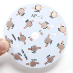
Many boards are the same circuit repeated. An eight channel amplifier, a four port transceiver, an LED driver array or a bank of identical sensor front ends: the schematic describes one channel and the layout has to place and route it several times. The repetition makes those boards quick to design and easy to get wrong, because an error that is made once is multiplied by the number of channels.
One Channel, Several Copies
The starting point is to make sure the repetition is real. Two channels are identical only if the schematic, the net naming and the component list are identical as well. A block that was copied in the schematic and then edited for one channel produces a layout where the copies are not interchangeable, and the module placement tools will place them as if they were.
The discipline that keeps this manageable is designator structuring. If every channel uses the same reference numeral offset, so that the first channel occupies one block of designators and the second occupies the next, then channel-to-channel correspondence is visible everywhere: in the schematic, in the bill of materials, in the placement data and in the test programme. When the designators are assigned in the order the parts were drawn, the same relationship has to be worked out by hand every time it is needed.
Net naming deserves the same treatment. Channel-prefixed net names, or a bus naming convention, make it possible to see at a glance whether a net belongs to one channel or is shared between all of them. The shared nets are the ones that need attention, because they are the connections that tie the channels together and they are where the repetition stops.

Repeating the Placement
Placing the copies is the easy part once the structure is right. The layout tool can copy a block of components and map the designators onto the corresponding components in the next channel, which is faster and more consistent than placing each part by hand.
The reason to use placement cloning rather than a careful manual placement is consistency of the electrical result. Two channels that are placed with the same relative positions have the same parasitic capacitance, the same trace lengths and the same thermal environment. Two channels placed by hand, even by the same engineer on the same afternoon, do not.
Where the design is defined as several instances of one schematic sheet, the layout tool can go further and treat the channels as a multi-channel design, placing one channel as a template and propagating it to the others. The advantage is that a later change to the template can be propagated again, so the channels stay consistent rather than drifting apart across revisions.
The container that makes this work is the room or the channel region. Defining a region around each channel gives the tool a boundary to work within, and it also gives the designer a way to check that each channel is complete before moving on.
Routing the Copies
Routing follows the same logic, with one addition: the routing has to be copied as well as the placement, and the copies have to obey the rules of the design.
For a digital multi-channel board, copying the routing gives equal lengths and equal loading everywhere, which is usually exactly what is wanted. For an analog or RF design, equal geometry is a starting point rather than the finish. Channel-to-channel matching becomes a specification, and phase differences between channels depend on the trace lengths and on the symmetry of the layout. Two channels whose traces are geometrically identical but which sit on opposite sides of a plane split will not behave identically.
The other consideration is coupling between adjacent channels. Repeating a block at the smallest possible spacing makes the board small and the channels close, and close channels couple: through the capacitance between adjacent traces, through a shared ground return, or through a shared supply. The usual mitigation is to keep the spacing between channels at least as wide as the spacing inside a channel, and to place a ground structure between them.
What the Shared Circuits Need
Every repeated block has a set of nets that are not repeated: the supply, the ground, the reference, the clock, the bias network and the control interface. Those are the nets where the design is not a copy, and they are where most of the review effort belongs.
A shared reference has to reach every channel with a voltage that is the same at each one, which means the copper from the reference source to the last channel has to be wide enough that the current of all the channels does not produce a gradient along it. The same applies to a shared bias current, where the trace resistance turns into a channel-to-channel offset.
A shared clock or a shared enable line has to reach the channels with the same delay and the same edge quality. If the line branches at a convenient point on the board, the last channel sees a longer stub and a different waveform, which shows up as a timing difference between channels that is present on every board from the design rather than as a manufacturing variation.
The supply is the structure most often under-designed in a repeated layout. Each channel draws its switching current locally, and the decoupling for each channel belongs beside that channel rather than at one point on the rail. A single bulk capacitor at the corner of the board does not help the channel at the far end, because the impedance of the trace between them is larger than the impedance the capacitor was added to reduce.
Verification
Checking a repeated layout is a comparison task rather than a design task, and it is worth automating.
The first check is completeness. Every channel should contain the same components and the same nets, and the fastest way to confirm it is to define each channel as a region and count the items in each one. A missing decoupling capacitor in channel five is invisible in a schematic review and obvious in a per-region count.
The second is geometric. The relative positions and the trace lengths of the channels should be compared, and any difference found should be explained by a deliberate decision rather than by an accident of manual placement.
The third is the shared network. The supply, the reference and the control signals should be traced from source to last channel, with the current path and the voltage gradient considered along the way. Where the design has a channel-to-channel matching requirement, that requirement belongs in the design rules so that a later edit cannot break it silently.
A repeated design also has a manufacturing consequence, because the same block is assembled several times on one board, and a pilot build therefore tests the channel design as well as the process. Our low volume PCB assembly service is often used at that stage. A defect that affects one component type will affect it in every channel, so the review of the assembly data is worth doing with the repetition in mind. Our design review checks per-channel consistency before release, and the placement and stencil decisions for a board of this kind are handled in our SMT assembly flow.
FAQ
Should every channel have identical routing? For digital channels, usually yes. For analog and RF channels, identical geometry is the starting point and the matching specification decides how far the symmetry has to go.
How wide should the spacing between channels be? At least as wide as the spacing inside a channel, with a ground structure between them where the coupling matters.
What is the most common error in a repeated layout? A shared net, usually a reference or a supply, that is routed as if it were local to one channel, so the last channel sees a different voltage from the first.