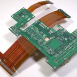
Rigid Flex Bend Area Design Rules
The Bend Area Is a Designed Feature
In a rigid flex assembly, the bend is not an accident of the shape; it is the reason the board exists. The flexible section lets a single circuit fold into a three dimensional product, eliminating connectors and cables, and the region that bends has to survive being folded during assembly and, in some products, being cycled in service. Every rule in rigid flex design exists because the bend area behaves differently from the rigid sections: it is thin, it has no stiffening material, it concentrates strain, and it is the part of the assembly that fails first when the geometry is wrong.
Where the Bend Should Sit
The bend must fall entirely within the flexible region, with clear distance on both sides from the rigid to flex transition. A common rule is to keep the bend at least one board thickness, and often two, away from the edge of the rigid material, because the transition zone contains the resin and adhesive that bonds the layers together and is brittle compared with the flex core. A bend that touches the rigid edge concentrates all the strain on that adhesive line and delaminates or cracks the copper. The flexible section also needs to be long enough: the length of the bend arc plus a margin depends on the bend radius, and a short flex length with a large radius is impossible. For a fold of one hundred and eighty degrees, the flex length must be at least the arc length of the two radii involved, and in practice a generous allowance is cheaper than a redesign.
Trace Direction and Copper Weight
Conductors should run perpendicular to the bend line wherever possible, so that each trace is bent across its width rather than stretched along its length. A trace that runs parallel to the bend line, and especially one that crosses the bend at an angle and then turns within the bend area, sees the highest strain and cracks first. Copper weight in the flex layers should be as thin as the circuit allows, usually one third of an ounce, and the traces should be evenly distributed across the width so that the flex does not curl. Plated through holes and vias are prohibited in the bend region, because a plated barrel cannot bend without cracking, and copper pours should be avoided or hatched in that area for the same reason that solid copper cracks.
Coverlay, Adhesive and Stiffeners
The coverlay protects the traces and controls the neutral axis. A laminated polyimide coverlay with adhesive is normal for a bend that will move, and a thinner adhesive layer usually gives better fatigue behaviour because less compliant material is stretching around the copper. Stiffeners, whether polyimide or FR-4, must stop well clear of the bend, and their boundary should be defined explicitly in the design data, because a stiffener that ends inside the bend creates a rigid to flexible transition in the worst possible place. Where a stiffener is needed close to a bend for connector support, the bend radius must be increased to compensate, and the transition should be separated by an air gap or a relieved region rather than a hard edge.

Bend Radius and Cycle Count
The minimum bend radius is quoted as a multiple of the total thickness of the flexible section, and it depends on the construction, the copper weight, the coverlay and whether the bend is static or dynamic. A single sided flex with a thin coverlay might allow ten times the thickness for a static bend; a multilayer rigid flex with a stiffener nearby may need thirty or more. These figures are starting points, not guarantees. For a bend that flexes in service, the honest specification is a radius, an angle and a cycle count, and the answer should come from a bend test on the actual construction. Where the product only folds once during assembly, the risk is different and usually lower, but the fold still has to survive the assembly fixture and the reflow that follows.
Mechanical Support and Assembly
Most rigid flex failures in production are caused by how the part is handled rather than by the design. A bend that is formed by hand has a different radius every time, and a fold that is clamped after forming holds the strain rather than relieving it. Designing relief features, such as a formed radius rather than a crease, a slot that allows the two rigid sections to approach each other, and a defined support in the assembly fixture, turns a marginal design into a reliable one. Where the fold is permanent, the fixture that holds it during the rest of the assembly should be part of the design review, because a bend that is strained while components are placed will damage joints as well as the flex.

FAQ
How far should a bend be from the rigid section? At least one, and preferably two, board thicknesses away from the edge of the rigid material, so that the strain is not concentrated at the adhesive transition.
Can vias be placed in a bend area? No. A plated barrel cannot flex without cracking, so vias and plated holes must be kept outside the bend region entirely.
Which direction should traces run? Perpendicular to the bend line, so the traces bend across their width rather than being stretched along their length.
What copper weight is used in a bend? As thin as the circuit allows, normally one third of an ounce, distributed evenly across the width of the flex.
How is bend radius specified? As a multiple of the flexible section thickness, with different values for static and dynamic bends, and it should be confirmed by a bend test for a moving application.
Conclusion
The bend area of a rigid flex board is a designed feature with its own rules: a defined radius, a location clear of the rigid transition, traces running across the bend rather than along it, no vias, thin copper and stiffeners that stop well away. Specify the radius, the angle and the cycle count, and confirm the construction with a bend test rather than with a rule of thumb. The flex construction limits are part of PCB capabilities, the routing and stiffener planning belongs in PCB design and layout, and the lamination and forming steps are described in PCB manufacturing. A prototype PCB assembly run with the real fixture proves the fold before volume in 2026.