Rigid-Flex PCB: PCB Design, PCB Manufacturing & Supplier Selection Guide
The demand for smaller, lighter, and more reliable electronic products continues to grow across aerospace, medical devices, telecommunications, automotive electronics, consumer electronics, industrial automation, and other advanced industries. As electronic systems become increasingly complex, manufacturers are looking for ways to achieve higher performance while reducing space, weight, and the number of electrical interconnections.
This trend has accelerated the adoption of rigid-flex printed circuit boards (PCBs).
Unlike conventional rigid PCBs or standalone flexible circuits, rigid-flex PCBs integrate rigid and flexible circuit sections into a single interconnected structure. This enables engineers to combine mechanical support with controlled flexibility, making rigid-flex technology particularly valuable for compact and space-constrained electronic products.
For engineers, purchasing teams, and product developers, understanding rigid-flex PCB construction, materials, advantages, applications, and manufacturing requirements is essential when selecting a reliable supplier.
This guide explains what rigid-flex PCBs are, how they are structured, their key advantages, where they are used, and what to consider when choosing a rigid-flex PCB manufacturing partner such as Kingda.
What Is a Rigid-Flex PCB?
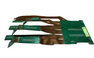
A rigid-flex PCB is a circuit board that combines rigid PCB sections with flexible circuit sections within one integrated construction.
The rigid areas provide mechanical support for components, connectors, and other electronic structures, while the flexible sections allow the circuit to bend, fold, or conform to the available installation space.
This hybrid structure eliminates some of the cables, connectors, and separate interconnection assemblies traditionally required to connect multiple rigid circuit boards.
As a result, rigid-flex technology can provide advantages in:
- Space utilization
- Weight reduction
- Mechanical integration
- Electrical reliability
- Assembly simplification
- Signal routing
- Product miniaturization
For modern PCB Design, rigid-flex technology provides engineers with significantly greater freedom than a conventional rigid circuit board.
How Is a Rigid-Flex PCB Constructed?
A rigid-flex PCB normally consists of one or more rigid PCB sections connected through flexible circuit areas.
The rigid sections are commonly constructed using materials such as FR-4, while the flexible sections typically use polyimide-based materials. Copper foil forms the conductive circuitry, while coverlay and other protective materials are used to protect flexible conductors.
A typical rigid-flex structure may include:
- Rigid laminate
- Flexible polyimide layers
- Copper foil
- Prepreg
- Adhesive systems where required
- Coverlay
- Solder mask
- Surface finish
- Silkscreen or other identification markings
- Plated through-holes and vias
The exact stack-up depends on the electrical requirements, bending requirements, number of layers, component placement, mechanical configuration, and manufacturing process.
Rigid Sections
The rigid portions provide mechanical stability and are generally used for mounting components, connectors, and other hardware.
FR-4 is widely used because it provides a practical balance of mechanical strength, electrical insulation, thermal stability, and cost.
Flexible Sections
The flexible portions allow the circuit to bend or fold.
Polyimide is widely used in flexible PCB construction because of its flexibility and thermal performance.
However, flexible circuit design requires careful control of copper geometry, bend radius, layer arrangement, coverlay, and mechanical stress.
Copper Conductors
Copper forms the electrical pathways throughout the rigid and flexible sections.
Copper thickness, trace width, spacing, and routing geometry must be selected according to current capacity, impedance, signal integrity, manufacturability, and bending requirements.
Rigid-Flex PCB vs. Conventional Rigid PCB
A conventional rigid PCB generally uses a rigid substrate and is not intended to flex during normal operation.
A flexible PCB, in contrast, is designed to bend and conform to different shapes but may not provide sufficient mechanical support for larger components.
Rigid-flex PCBs combine these characteristics.
The rigid portions provide mechanical support where components need to be mounted, while the flexible portions provide controlled movement or three-dimensional routing where space is limited.
This makes rigid-flex technology particularly useful when several circuit boards would otherwise need to be connected using cables or connectors.
Key Advantages of Rigid-Flex PCBs
Rigid-flex technology offers several advantages over conventional multi-board assemblies.
1. Reduced Size and Weight
One of the biggest advantages of rigid-flex PCBs is their ability to reduce the overall size and weight of an electronic assembly.
Flexible sections can be folded into available spaces, allowing designers to optimize the internal layout of the product.
The elimination of some cables and connectors can further reduce assembly volume and weight.
This is particularly useful for:
- Wearable devices
- Portable medical equipment
- Smartphones
- Cameras
- Aerospace electronics
- Compact industrial equipment
2. Improved Reliability
Traditional cable-based assemblies can contain numerous connectors, solder joints, wires, and mechanical interfaces.
Each additional interconnection can introduce another potential failure point.
A properly designed rigid-flex PCB can consolidate multiple interconnections into one integrated circuit structure, potentially reducing mechanical and electrical failure risks.
Rigid-flex assemblies can also be designed to withstand vibration and mechanical movement when the materials, bend radius, and construction are properly selected.
3. Better Signal Integrity
As electronic systems operate at higher speeds and frequencies, signal integrity becomes increasingly important.
A rigid-flex design can reduce the number of discrete connectors and interconnection transitions between circuit sections.
Shorter and better-controlled signal paths can help reduce parasitic effects and unwanted discontinuities.
However, rigid-flex does not automatically guarantee superior signal integrity. High-speed designs still require appropriate impedance control, stack-up engineering, return-path planning, connector selection, and transmission-line analysis.
4. Greater Design Flexibility
Rigid-flex technology allows engineers to design electronic assemblies around the mechanical structure of a product.
Instead of forcing the product enclosure to accommodate several rigid circuit boards, the PCB can be shaped to fit the available space.
This makes three-dimensional electronic architectures possible.
For example, rigid sections can be positioned on different planes and connected by flexible sections that fold around mechanical structures.
5. Simplified Assembly
Replacing multiple cables and connectors with an integrated rigid-flex structure can simplify assembly.
A simpler interconnection architecture can reduce:
- Connector count
- Cable routing
- Manual assembly operations
- Wiring errors
- Assembly space
- Maintenance complexity
Although the initial rigid-flex PCB fabrication cost may be higher than that of a conventional rigid PCB, the total system cost can be lower when reduced assembly complexity and improved reliability are considered.
Materials Commonly Used in Rigid-Flex PCB Manufacturing
Material selection has a major impact on rigid-flex PCB performance.
Common materials include:
FR-4
FR-4 is widely used for the rigid portions of rigid-flex boards.
Its combination of mechanical strength, electrical insulation, flame resistance, and cost effectiveness makes it suitable for many commercial and industrial applications.
Polyimide
Polyimide is one of the most important materials for flexible circuit sections.
It provides flexibility and good thermal performance, making it suitable for applications where the circuit must bend or occupy a limited three-dimensional space.
Copper
Copper is used for signal and power conductors.
For flexible sections, engineers must consider copper type and thickness carefully because repeated bending can create mechanical stress in the copper.
Coverlay
Coverlay is commonly used to protect exposed conductors on flexible sections.
It provides electrical insulation and mechanical protection while maintaining the flexibility of the circuit.
Adhesive and Bonding Materials
Depending on the construction, specialized adhesive or bonding systems may be used to integrate flexible and rigid sections.
Material compatibility is important because different materials have different thermal expansion and mechanical characteristics.
Rigid-Flex PCB Manufacturing Process
Rigid-flex manufacturing is more complex than conventional rigid PCB fabrication because the manufacturer must manage both rigid and flexible structures within a single product.
A typical PCB Manufacturing process may include:
- Engineering and stack-up review
- Material selection
- Inner-layer circuit fabrication
- Flexible-layer processing
- Layer alignment
- Lamination
- Drilling and/or laser drilling
- Desmear and hole preparation
- Copper plating
- Outer-layer circuit formation
- Solder mask and coverlay processing
- Surface finishing
- Routing and profiling
- Electrical testing
- AOI and other inspections
- Final quality inspection
The exact process depends on the rigid-flex construction and product specifications.
Important Rigid-Flex PCB Design Considerations
Successful rigid-flex products begin with a carefully engineered PCB Design.
Bend Radius
Bend radius is one of the most important parameters.
If a flexible section is bent beyond its allowable radius, the copper and dielectric materials may experience excessive mechanical stress.
The required bend radius depends on factors such as:
- Total flexible thickness
- Number of conductive layers
- Copper type
- Copper thickness
- Static or dynamic bending
- Material properties
- Expected number of bending cycles
Therefore, bend requirements should be defined before manufacturing begins.
Flexible Area Geometry
The transition between rigid and flexible sections requires careful design.
Abrupt geometry changes can create stress concentrations. Engineers should use appropriate transition structures and avoid placing unnecessary mechanical stress directly at the rigid-flex interface.
Component Placement
Components should generally be mounted on rigid areas unless the component and flexible construction have specifically been designed for flexing.
Heavy components can generate significant mechanical stress on flexible regions.
Copper Routing
Trace routing in flexible sections should account for bending and mechanical stress.
Designers should avoid unnecessary sharp corners and structures that can concentrate stress.
Layer Stack-Up
The rigid-flex stack-up must be designed around both electrical and mechanical requirements.
For high-speed products, impedance control and signal integrity remain important. For mechanically dynamic products, flex durability may be the dominant consideration.
The final stack-up must therefore balance:
- Electrical performance
- Mechanical flexibility
- Thermal performance
- Manufacturing capability
- Reliability
- Cost
Applications of Rigid-Flex PCBs
Rigid-flex technology is used across many industries where compactness, reliability, and mechanical integration are important.
Aerospace and Defense
Aerospace electronics must operate under demanding environmental conditions.
Rigid-flex PCBs can help reduce weight, save installation space, and reduce the number of mechanical interconnections.
Potential applications include avionics, navigation equipment, sensors, communication systems, and other mission-critical electronics.
Medical Devices
Medical equipment increasingly requires compact and highly reliable electronic assemblies.
Rigid-flex PCBs can be used in:
- Diagnostic equipment
- Patient monitoring systems
- Medical imaging equipment
- Portable medical devices
- Wearable medical electronics
Reliability, cleanliness, material qualification, and regulatory requirements should be evaluated carefully for medical applications.
Automotive Electronics
Modern vehicles contain increasingly complex electronic systems.
Rigid-flex PCBs can support applications such as:
- Advanced driver assistance systems (ADAS)
- Battery management systems
- Vehicle sensors
- Infotainment
- Lighting systems
- Electronic control systems
Automotive applications often require resistance to vibration, temperature cycling, and other environmental stresses.
Consumer Electronics
Smartphones, tablets, cameras, wearable devices, and gaming equipment all require compact internal electronics.
Rigid-flex designs allow manufacturers to integrate electronics into limited spaces while maintaining mechanical freedom.
Telecommunications
High-speed communication systems require reliable electrical interconnections and controlled signal performance.
Rigid-flex structures can help reduce connector count and optimize internal routing in selected telecommunications equipment.
Industrial Automation
Industrial systems often operate in environments involving vibration, temperature variation, and mechanical movement.
Rigid-flex PCBs can be used in robotics, sensors, industrial controllers, instrumentation, and factory automation equipment.
How to Choose a Rigid-Flex PCB Manufacturer
Selecting a reliable rigid-flex PCB supplier is an important part of product development.
Not every PCB manufacturer has the equipment, engineering experience, materials, and process controls necessary to produce complex rigid-flex boards consistently.
Evaluate Technical Capabilities
Before selecting a supplier, evaluate:
- Rigid-flex experience
- Layer-count capability
- HDI capability
- Minimum trace and spacing
- Minimum hole size
- Flexible section capability
- Material options
- Copper thickness range
- Impedance control
- Manufacturing tolerances
The supplier should demonstrate that its manufacturing processes are compatible with the project’s technical requirements.
Review Quality Certifications
Quality management systems provide an important indication of manufacturing maturity.
Depending on the application, relevant certifications and standards may include:
- ISO 9001
- ISO 13485
- IATF 16949
- AS9100
- IPC standards
- RoHS and REACH compliance
The appropriate requirements depend on the end-use industry.
Assess Production Capacity
A supplier should be able to support the complete product lifecycle, from prototype development to volume production.
Production scalability is particularly important for products expected to move rapidly from engineering validation to mass production.
Examine Quality Control
A reliable rigid-flex manufacturing process should incorporate appropriate inspection and testing.
Potential quality controls include:
- DFM review
- Material verification
- AOI
- X-ray inspection where applicable
- Dimensional inspection
- Electrical testing
- Impedance testing
- Microsection analysis
- Process monitoring
- Final inspection
Consider Engineering Support
Rigid-flex PCB projects often require closer communication between the designer and manufacturer than conventional rigid PCB projects.
A capable supplier should be able to review:
- Stack-up
- Bend requirements
- Material selection
- Hole structures
- Layer transitions
- Component placement
- Manufacturing tolerances
- DFM considerations
Early engineering collaboration can identify potential manufacturing problems before production begins.
Compare Total Cost
The lowest PCB quotation is not necessarily the lowest total cost.
Procurement teams should consider:
- PCB fabrication cost
- Assembly cost
- Connector reduction
- Cable reduction
- Engineering support
- Yield
- Quality
- Delivery time
- Long-term reliability
A higher-quality manufacturing partner may deliver better overall value by reducing assembly complexity, defects, redesigns, and production delays.
Why Choose Kingda for Rigid-Flex PCB Projects?
Kingda provides integrated PCB and PCBA manufacturing services designed to support projects from engineering development through production.
Its capabilities cover PCB design support, PCB fabrication, component sourcing, SMT assembly, through-hole assembly, inspection, testing, and final integration.
For rigid-flex projects, an integrated manufacturing approach can help engineers coordinate material selection, PCB fabrication, assembly, and quality requirements within a unified production workflow.
Kingda can also support a range of advanced PCB requirements, including multilayer, HDI, high-frequency, high-Tg, rigid-flex, heavy-copper, and other specialized PCB constructions.
For customers developing automotive electronics, industrial equipment, telecommunications products, medical devices, or other advanced electronic systems, early collaboration between PCB Design and PCB Manufacturing teams can help improve manufacturability and reduce engineering risk.
Final Summary
Rigid-flex PCBs combine the mechanical strength of rigid circuit boards with the flexibility of flexible circuits in a single integrated structure.
Their ability to reduce space and weight, simplify interconnections, improve mechanical integration, and potentially enhance system reliability makes them increasingly important for modern electronic products.
However, rigid-flex PCB technology requires careful attention to materials, bend radius, copper routing, layer stack-up, rigid-flex transitions, component placement, and manufacturing tolerances.
Choosing an experienced manufacturing partner is therefore critical. From initial PCB Design and DFM analysis to fabrication, PCB Manufacturing, assembly, inspection, and testing, every stage can influence the final product’s reliability and performance.
For demanding rigid-flex PCB projects, Kingda provides integrated PCB and PCBA capabilities that can help turn complex circuit requirements into manufacturable and reliable electronic assemblies.