RS485 Testing on a Smart Meter Communication Board
A smart meter communication board can power up correctly and still fail in the field, because the behaviour that matters is only visible under repeated traffic. A board may answer the first request after a cold start and then stop, lose an occasional frame during a long polling cycle, transmit correctly and receive nothing, or fail on the first power-up and recover after a restart. Those are different faults and they route to different causes, so the work begins by defining which one is being looked for and under what supply, baud rate, address, frame format and termination the result will be judged.
Fix the Acceptance Condition First
RS485 testing starts with the acceptance condition rather than with the instrument. The supply voltage and its tolerance, the baud rate and the frame format, the node address, the direction control, the termination arrangement and the number of boards sharing the bus all belong in writing before a single frame is sent. Without that baseline, a board that passes on one bench and fails on another cannot be traced back to a cause at all.
The reason this matters for a smart meter communication board is that the same product is often built in several hardware versions and with several program versions in circulation. A result recorded against one combination says nothing about another. The test record has to name the board revision, the program revision and the test configuration together, otherwise a later failure cannot be reproduced.
The customer package should carry the Gerber data, the bill of materials, the placement coordinates, the assembly drawing, the program file, the protocol definition and the interface definition. Where the board also includes metering, display or other functions, the scope of this order has to state which of them are being verified and which are out of range.
Review the Bill of Materials Against the Test Setup
Before production, the transceiver part number, the protection devices, the termination resistors and the interface connector are compared with the configuration the test will use. Parts that carry the same outline can differ in drive strength, slew rate limiting, fail-safe behaviour and supply range, and those differences show up as intermittent faults rather than as a hard failure.
Boards that select a termination or a communication mode by fitted resistors are a frequent source of confusion. If the bill of materials says only that the part is fitted as required, the line cannot know whether the current version needs it, and a batch ends up with mixed configurations that are indistinguishable on the bench. The fitted or not-fitted state belongs in the document as a definite instruction.
Inspect the Interface Before Sending Anything
After SMT assembly, the interface device, the connector, the protection parts and the surrounding passives are inspected before the board is powered. A fine-pitch lead bridge, a connector pin that did not wet, or a protection device placed the wrong way round all produce the same symptom as a software problem while having nothing to do with it.
The inspection is followed by a current limited power-up, with the static current compared against the range the customer gives. A current well outside that range is a reason to stop and look for a shorted rail, a reversed device or a wrong part before any test equipment is connected. Once the supply is acceptable, the transceiver rail, the enable signal and the idle state of the bus are checked.
Only one variable is changed at a time from that point. Changing the program, the cable and the test master together may restore communication while destroying the evidence of what actually caused the failure.
Compare Waveforms Rather Than Replugging
A known good fixture, cable and reference board give the baseline. An abnormal board is then measured under the same conditions so that the transmit, receive and direction control states can be compared directly. If the driver input moves but nothing appears at the device output, the problem is at or before the transceiver. If the device output is correct and the connector is not, the path through the protection parts and the connector becomes the subject.
For faults that appear only occasionally, repeated power cycles and a continuous exchange are the useful additions, but the number of cycles, the duration and the permitted error rate have to come from the customer or from a joint agreement. Where the anomaly depends on cable length, on the termination fitted or on how many nodes are attached, the condition is fixed before the comparison, because an external bus problem attributed to the board leads to a repair that never closes.
An oscilloscope helps to see how the differential pair behaves, but the reading is still judged against the interface definition and the acceptance condition. Probe loading, the reference ground and the fixture itself change what appears on the screen, so an unexpected trace is first checked for a sound connection rather than assumed to be a board defect.
Requalify After a Repair
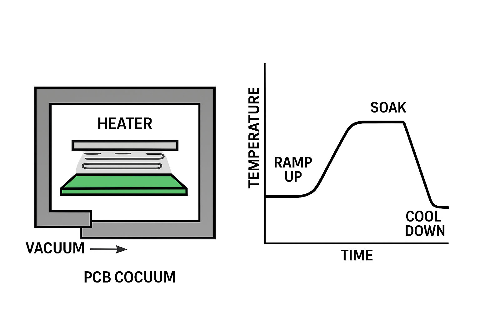
Where the cause turns out to be the transceiver, a termination resistor or the connector joint, the repair is done with the heated area controlled so that neighbouring parts are not disturbed. After the repair the board does not go straight to packing. The power-up current, the program check, the continuous exchange and the repeated start sequence all run again.
A single successful exchange proves that the board can work, not that the intermittent fault is gone. The evidence that closes the case is the same sequence of tests repeated often enough, under the same conditions, to show that the failure rate has returned to the accepted level. The pass and fail counts are recorded per board rather than as a single verdict for the batch, so that a board which passed on a retry can still be recognised as one that failed once.
Records and Despatch
The delivery record carries the hardware revision, the program revision and the test state that were agreed, so that the customer can match the board in hand with the result. Connectors and other protruding parts are protected for transport, because a bent terminal that arrives at the assembly line looks exactly like a process defect.
Where the customer also needs through-hole parts, enclosure assembly or system level testing, the assembly drawing and the harness definition are needed at the quotation stage rather than after the boards are built. Our industrial PCBA line handles the assembly, programming and interface testing, and the results are retained with the build under our quality management system, while boards that need the harness and system level work go through box build assembly.
FAQ
Why does a board pass on the bench and fail in the meter? Because the bench does not reproduce the bus length, the node count or the polling pattern of the installed system. The test condition has to be documented before the result means anything.
Should the program be changed during fault finding? Not at the same time as the cable or the fixture. One change at a time is what makes the cause identifiable.
Is a single successful transmission enough after repair? No. The intermittent behaviour has to be re-tested with the repeated sequence that originally exposed it.