Security Camera PCB: Design, Materials and Manufacturing
What a Security Camera PCB Is
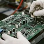
A security camera board is the interconnect at the centre of a surveillance device, and the scope is wider than the name suggests. It covers the main board of a mains powered network camera, the compact assembly inside a smart doorbell, the controller in an access control reader, the detector board in an infrared alarm and the computing board in an edge AI video terminal. Vehicle mounted cameras and machine vision heads use the same building blocks under harsher conditions. What they share is a demanding combination of a sensitive analogue front end, a fast digital signal path, a bursty high current load, a wireless radio and a housing that is often sealed and passively cooled.
What the Board Has to Do
Deliver clean power. The image sensor is the most noise sensitive part of the system, and its analogue supplies have to be separated from the switching regulators that feed the processor. A camera that produces banding in low light almost always has a power integrity problem rather than an optical one.
Carry the image data. The link between the sensor and the image signal processor is a high speed differential interface, which means controlled impedance, matched lengths and a continuous reference plane from the connector to the processor pins.
Return the data. Networked cameras carry an Ethernet or wireless interface, and both bring their own layout requirements: a controlled impedance pair and magnetics for one, an antenna keepout and a quiet ground for the other.
Drive the illumination. Infrared LEDs are switched at high current in short pulses, so the board has to deliver a step load without disturbing the sensor supply and without radiating into the antenna. This is where copper weight, decoupling and loop area decide whether night images are clean.
Move and sense. Pan and tilt mechanisms add motor drives and position sensors, and they add vibration that the connectors and the mounting features have to tolerate. Audio input adds a microphone that must be kept away from switching supplies and from mechanical noise coupling.
The Boards Inside a Camera
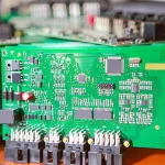
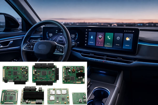
Most cameras are built from three or four separate boards rather than one. The sensor board carries the image sensor and its support circuitry and has to be positioned precisely relative to the lens. The main board holds the processor, memory, power conversion and network interface. The infrared board carries the LED array and its driver and is frequently built on a metal core laminate because the LEDs generate most of the heat in the product. A flexible circuit or a rigid flex assembly connects the sensor board to the main board in compact designs, and in pan and tilt products it also has to survive continuous flexing. Splitting the electronics this way keeps the sensitive analogue section away from the heat and the switching noise, and it lets each board use the material it actually needs.
Materials and Why They Are Chosen
Standard high glass transition FR-4 covers the main board in most products. A metal core aluminium board is common for the infrared array, because the aluminium spreads heat laterally and the dielectric layer provides electrical isolation despite being only tens of micrometres thick. Wireless heavy designs may move to a low loss laminate if the radio path is long or the antenna is integrated into the board. Flexible polyimide appears in the sensor and gimbal connections, where thinness and bend radius matter more than stiffness. Sealed outdoor products add a conformal coating, and the coating choice has to be compatible with the connector and with the optical path, since a coating that migrates onto a lens or an infrared filter is a defect rather than a protection.
Design Points That Decide Image Quality
Keep the sensor supply and the ground return separate and short, and treat the analogue and digital grounds as a deliberate single point connection rather than a natural consequence of the pour. Route the high speed image interface as a controlled impedance pair over a continuous plane, match its length, and keep it away from the switching regulators. Place decoupling for the image sensor at the pins rather than at the edge of the board. Size the copper for the infrared burst current instead of for the average, and keep the LED current loop small so it does not couple into the sensor or the radio. Respect the antenna keepout, and keep the ground under the radio continuous and stitched. Control the thermals: the processor and the sensor both drift if they run hot, and sensor temperature affects dark current, so the heat path from the processor to the housing should not pass through the sensor. For outdoor products, plan the moisture path and the coating, and for pan and tilt products, plan the strain relief on every cable.
Manufacturing Requirements
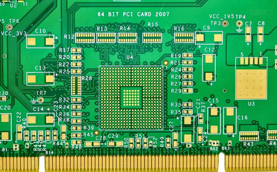
The image interface and any high speed link need impedance control verified by coupon. Fine pitch packages on the processor call for tight registration and for a surface finish that survives multiple reflow cycles, which is why a flat finish such as electroless nickel immersion gold is common on camera boards. Metal core boards require their own process for drilling and for the dielectric, and they need care in the reflow profile because the aluminium conducts heat away from the joint. Conformal coating has to be applied so that the thickness is controlled and the connectors, test points and optical surfaces remain clean. The board thickness and flatness matter more than usual because the sensor has to sit at a defined distance from the lens, and a warped board changes the focus across the field of view.
What Drives the Cost
Layer count and board size set the base cost, and camera boards are usually small but dense, so the price per square metre is high while the price per board stays moderate. The materials add their own premium: aluminium metal core, low loss laminate and polyimide flex each cost more than standard FR-4. Impedance control, fine line widths, tight registration and a flat surface finish are all extra process steps. Conformal coating, if required, is another operation. In volume the per piece price falls, but the tooling and the first article inspection for a metal core infrared board or a rigid flex assembly do not disappear, which is why low volume camera development is more expensive than the board area alone would suggest.
Where the Technology Is Heading
Resolution is moving from two megapixels to four, eight and beyond, which raises the interface rate and makes impedance control and loss management non optional. Edge AI is putting inference into the camera, which means a faster processor, more memory, more power and a larger thermal problem in the same sealed housing. Wireless cameras and battery powered models demand lower standby current, which favours more efficient conversion and more careful layout of the always on sections. Vehicle and machine vision applications are pushing toward higher temperature ratings and toward automotive grade qualification. In every case the electrical architecture grows and the mechanical envelope does not.
FAQ
Why do camera boards use a metal core PCB? The infrared LED array generates most of the heat in the product, and an aluminium substrate spreads it laterally far better than FR-4 while still providing electrical isolation.
What surface finish suits a camera board? A flat finish such as electroless nickel immersion gold is common, because it survives multiple reflow cycles and provides a coplanar surface for fine pitch packages and for the image sensor pads.
Do security cameras need conformal coating? Outdoor units should be coated to resist humidity and condensation, and the coating must be controlled so that connectors, test points and optical surfaces are not contaminated.
How is the image sensor connected to the processor? Through a high speed differential interface, typically a MIPI link, routed as an impedance controlled pair over a continuous reference plane.
What limits the low light performance of a camera board? Power integrity and thermal drift more often than the sensor itself. Noise on the analogue supply and heat reaching the sensor both degrade dark performance.
Conclusion
A camera board is a mixed signal design with a thermal problem and a mechanical precision requirement attached. Keep the analogue front end quiet, route the image interface over a solid reference, size the copper for the infrared burst rather than the average, control the heat path so the sensor stays cool, and respect the antenna and coating requirements of the enclosure. Then confirm the stackup and the surface finish with the fabricator, because a camera board is judged by an image rather than by a measurement. The material and process limits are listed in PCB capabilities, the mixed signal layout conventions belong in PCB design and layout, and the coating and inspection steps are described in PCB manufacturing. A prototype PCB assembly build with the real lens and housing is the only reliable way to find the thermal and alignment issues before volume in 2026.