Security Surveillance PCB Manufacturing for Reliable Systems
Surveillance hardware rarely fails on the day it is installed. It fails months later, after heat, humidity and continuous power have worked on a marginal joint or a drifting impedance. That is why security surveillance PCB manufacturing deserves more attention than a simple quote comparison. The board carries image data, power and control signals at the same time, often inside a sealed enclosure. This guide explains where reliability is won or lost, and what buyers should verify before releasing a build.
A surveillance board is not a generic digital board with a camera connector attached. It must hold stable electrical performance while handling high-speed image data, power distribution and electromagnetic noise together. Higher resolutions, edge processing and compact enclosures push those requirements further. The sections below follow the board from design choices through fabrication, assembly and test. Each stage leaves evidence, and that evidence is what separates a repeatable supplier from a lucky one.
Why Uptime Starts at the Board
Security equipment is often expected to run without interruption for long periods. A camera on a commercial building, a traffic pole or an industrial site may have limited maintenance access. When the board stops working, the system stops recording, and the cost is not only the replacement part. Board reliability therefore affects system availability directly. A stable platform supports sensor communication, processor and memory interconnection, power delivery, network links and alarm handling.
Reviewing these functions early is part of good PCB design and layout practice, because most field failures trace back to decisions made before fabrication.
Initial functional testing does not prove long-term stability. A board can pass at room temperature and still fail after thermal cycling or months of continuous operation. Buyers should ask how the supplier verifies performance beyond first power-up. Process records, inspection data and test coverage tell you more than a sample that happens to work. The same discipline applies to security surveillance PCB builds, where a small process drift can become a large yield loss. Documenting the agreed parameters keeps engineering, assembly and test teams working from the same numbers.
Power Delivery and Thermal Control
Surveillance boards pack processors, image sensors, memory, communication modules and infrared LEDs into a small area. The power distribution network must supply adequate current and keep voltage fluctuations small. Power and ground planes, suitable copper thickness, proper decoupling and short return paths all help. Heat is the second half of the problem. Processors, regulators and infrared LEDs create local hot spots inside a closed housing. If that heat cannot spread, component life and electrical performance both suffer.
Thermal planning should start with the real power dissipation and the actual enclosure, not with a generic rule.
Large copper areas, thermal vias, dedicated ground planes and sensible component placement are common tools. The stack-up can also be arranged to move heat away from sensitive parts. For security surveillance PCB projects, the figures that matter are measured rather than assumed. Ask for the thermal assumptions used during design review and check them against the enclosure drawings. A board that runs cool on the bench may behave differently inside a sealed dome in direct sun.
Buyers should confirm that the supplier reviewed the mechanical and thermal context, not just the Gerber files.
Signal Integrity at Higher Data Rates
Modern cameras process high-resolution video and large amounts of sensor data. As data rates rise, layout and material choices matter more. Impedance discontinuities, long traces, poor return paths and crosstalk all degrade the signal. Controlled impedance, differential-pair routing and continuous reference planes reduce that risk. Via transitions deserve attention too, because each one changes the return path. A stack-up built for high-speed interfaces keeps noisy and sensitive circuits apart. Suppliers who understand these constraints will ask about interface types before quoting, rather than after the first article fails.
Electromagnetic interference is closely related. Surveillance equipment often sits beside wireless modules, motors, switching regulators and power circuits. Ground-plane design, shorter high-speed paths and differential signaling help contain noise. Shielding structures may be needed in some designs. Treating EMI as a final test problem is expensive, because layout changes at that stage usually mean a new board revision. Buyers should confirm that interference control was part of the design review. The right time to fix a return-path problem is before tooling, not after the first lot ships.

Environmental Resistance and Materials
Surveillance boards operate from climate-controlled rooms to outdoor poles. Temperature swings, humidity, condensation, dust, vibration and corrosive air all affect long-term reliability. Standard FR-4 suits many indoor products. High-Tg laminates or other specialized materials may be justified when the environment is harsh or the thermal load is high. Material choice should follow the operating temperature, thermal cycling, moisture absorption and mechanical needs of the product. Selecting laminate purely on cost can shift the risk to the field, where repair is far more expensive than the material upgrade would have been.
Surface finish affects solderability, corrosion resistance and contact performance. ENIG, HASL and OSP each suit different situations, and the choice should match the assembly process and the exposure. For humid or contaminated environments, conformal coating at the assembly stage adds protection. Coating is not a substitute for a clean process, however. Residues trapped under a coating can cause problems later. Buyers should confirm the cleaning step, the coating type and the inspection method together. These details belong in the process documentation, not in a verbal promise during the supplier visit.
Fabrication Steps That Carry Risk
Every fabrication stage can influence final performance. Engineering review comes first, and DFM analysis should catch trace width, spacing, hole size and copper distribution issues before tooling. Lamination control affects layer registration and dielectric thickness, which in turn affect impedance. Drilling quality and plating thickness determine whether vias connect reliably across many layers. Solder mask clearance and surface finish influence assembly yield. Electrical testing then screens open and short circuits before the board reaches the line.
A supplier that tracks these steps can show records. A supplier that cannot may still build good boards, but you have no evidence until something fails.
Multilayer technology lets designers separate power, ground, high-speed and low-speed signals across layers. That improves routing density and signal quality while keeping the board compact. The stack-up must be engineered carefully, because dielectric thickness, copper weight and reference-plane position all change electrical behavior. For complex products, the board structure should be developed alongside the enclosure, the component placement and the assembly process. Buyers comparing quotes should check whether the stack-up was reviewed or simply copied from an older project.
That single question often reveals how much engineering attention the supplier will give the build.
Assembly Quality and Test Coverage
The bare board is only part of the system. Placement accuracy, solder volume and reflow profile decide whether the finished assembly works. SMT lines handle compact processors, memory and sensors, while through-hole parts provide mechanical strength for connectors and power terminals. Inspection methods such as solder paste inspection, optical inspection and X-ray each cover different defect types. Electrical and functional testing confirm behavior under power. A structured PCBA testing plan closes the loop between inspection findings and process settings. That feedback is what lowers defect rates over successive lots.
Test coverage should match the product, not a default template. A camera board with high-speed interfaces needs different checks than an access control terminal with relays and displays. Buyers should ask which tests run on every unit and which run on samples only. They should also ask how failures are handled and whether the results are kept with the lot record. That record provides the quickest path to the root cause when a field return shows up months later.
Suppliers who treat testing as a cost center tend to cut it first. Suppliers who treat it as feedback keep improving the process.
Matching the Board to the Product
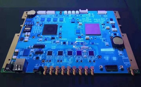
Not every security device has the same requirements. Cameras need compact boards with image sensors, processors, network interfaces and infrared control. Industrial monitoring equipment needs stronger resistance to vibration and electrical noise. Traffic systems face outdoor temperature swings and continuous power. Access control terminals combine RFID, biometrics, displays and communication on a small board. Each case shifts the priorities between signal integrity, thermal design and environmental protection. A supplier who builds all four the same way is probably not reviewing the application.
Buyers should describe the installation environment clearly and ask how it changes the design and process choices.
Quality control should cover the whole chain rather than the final inspection station. Material verification, lamination control, copper thickness, hole quality and layer registration all feed the result. Production traceability ties each board to its process data. When the product moves from prototype to volume, the same controls should follow it. A practical development path includes design review, prototype fabrication, prototype assembly, functional testing and a pilot run before volume. Buyers who invest in that sequence usually reach stable production faster.
The PCB assembly stage is where many of those early lessons become visible.
What to Confirm Before Release
Before releasing a build, confirm the stack-up, the impedance targets and the material grade against the application. Check the thermal assumptions against the enclosure. Confirm the surface finish and any coating requirement. Ask which inspection and test steps run on every unit, and request the records that prove it. Confirm how changes are communicated and how repeat orders are kept consistent. These questions cost little and remove most of the risk from the project.
A supplier who answers them with data is easier to trust than one who answers with assurances. The turnkey PCB assembly route can simplify this if one partner controls fabrication, sourcing and assembly.
Prototypes are the cheapest place to find problems. Early samples reveal pad geometry issues, component tolerances and process behavior before large volumes are committed. Small-batch SMT PCB assembly lets engineers validate the design under realistic conditions. The lessons from that stage should feed back into the fabrication drawings and the inspection plan. When the design is stable, the same parameters should carry into volume production without quiet changes. Buyers should ask how the supplier preserves those settings across repeat orders.
Consistency between the first lot and the tenth is the clearest sign that the process is under control.
The final takeaway is simple. Reliability in surveillance electronics comes from decisions made before fabrication and checks kept during production. Confirm the stack-up, the thermal path, the finish, the test plan and the traceability records before you release the order. Then verify that the same parameters appear in the first article report and in every repeat lot. That habit protects the schedule, the field performance and the reputation of the product.