Small-Batch PCB Prototyping for Surveillance Systems
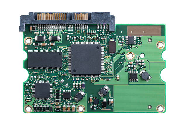
Security cameras and monitoring units now run continuously, often in hot cabinets or outdoor enclosures. The PCB inside carries image sensors, processors, memory, network interfaces and power circuits on a shrinking board. A design that looks correct in CAD can still fail once it becomes a physical board. Small-batch prototyping exists to close that gap before tooling and volume orders are committed. The goal is simple: build a few boards, measure them, and fix the design while changes are still cheap.
For buyers, the prototype stage is where cost and schedule are really decided. A rushed sample run produces unreliable data, and unreliable data leads to wrong conclusions. A careful run produces boards that represent the final product closely enough to trust. That difference matters most for surveillance hardware, where one board may serve a product family for years. This review sets out what to check at each stage, from stackup and materials through assembly, test and the move to volume.
Why Prototypes Come First
Surveillance products rarely move straight from concept to mass production. Specifications shift as image resolution, processing power and enclosure size change during development. Building thousands of boards before the design is settled ties up material and tooling money in a solution that may still change. A small prototype lot lets engineers test real hardware under realistic conditions. They can confirm signal behavior, thermal margins, mechanical fit and component compatibility. Each finding feeds back into the layout or the fabrication notes.
The prototype also acts as a rehearsal for production. Process engineers see which features are tight, which layers are demanding, and where inspection needs more attention. That knowledge shortens the ramp when volume begins. Buyers should treat the prototype order as an engineering deliverable, not just a purchase of samples. Ask for the fabrication notes, the stackup drawing and the test results together. Those documents show whether the design was actually validated or merely built.
Stackup Choices
Most surveillance control boards start on standard FR-4 with a conventional layer count. That is often enough for power management, sensor interfaces and low-speed control. Once the design adds high-speed camera links, gigabit networking or dense processor buses, the stackup becomes a performance decision. Reference planes, dielectric thickness and layer spacing control impedance and return paths. Engineers should define these values before quoting, not after the first boards arrive. A stackup drawn only to hit a layer count usually causes problems later.
Material choice follows the same logic. Higher operating temperatures, compact enclosures and demanding electrical performance may justify higher-grade laminates. Standard material may be fine for a control board that sits in a ventilated housing. The prototype is the right place to compare options with real measurements. Buyers should ask which material was used and why, and keep that record with the design files. A material change made quietly at volume can shift impedance and thermal behavior in ways the prototype never tested.
Layout and Signal Integrity
Layout decisions dominate high-speed surveillance designs. Trace geometry, grounding, return paths and layer transitions all affect signal quality. A camera interface that works on the bench may show errors once the board sits inside a metal enclosure with other electronics. The prototype lets engineers observe those effects directly. They can compare measured behavior against the design intent and adjust routing before the design freezes. Good layout support during this phase reduces the number of build cycles needed.
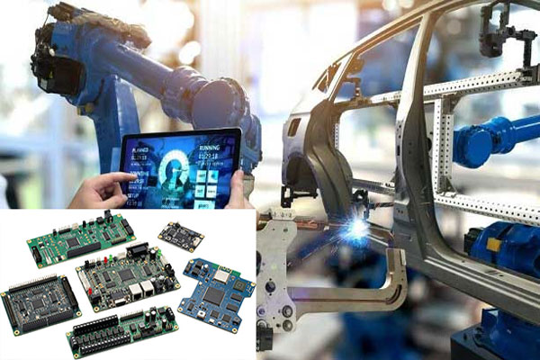
Electromagnetic compatibility deserves early attention as well. Surveillance devices often combine switching power supplies, clocked processors and sensitive analog front ends on one board. Separation, shielding and filtering decisions belong in the layout, not in a late patch. Prototype boards give the team a chance to check emissions and immunity behavior before certification testing. Fixing a grounding problem on a prototype costs a revision. Fixing it after a failed compliance test costs schedule and credibility. Teams planning this work can review rapid PCBA prototyping options early.
Assembly and Test Coverage
Bare boards are only half the validation. The assembled prototype shows whether the design survives real soldering, handling and power-up. Fine-pitch components, thermal pads and connectors each bring their own assembly risk. Engineers should confirm that the chosen surface finish, stencil design and reflow profile suit the component mix. A prototype built with a stable SMT PCB assembly process gives test results that can be trusted. Boards assembled with unclear process control can fail for reasons unrelated to the design.
Test coverage should match the risks in the design. Electrical continuity checks catch opens and shorts, while functional test confirms that interfaces, memory and power rails behave as intended. Boundary scan or in-circuit test helps where dense digital logic makes probing difficult. A structured PCBA testing plan records what passed and what failed, and why. Those records become the baseline for volume. If a prototype passes only after a manual rework step, that step must be designed out before production begins.
Quality Records That Matter
Prototype quality should not be treated as optional because the quantity is small. These boards drive engineering decisions, so inaccurate samples mislead the whole team. Fabrication should include design file review, material verification, process control and final inspection. Assembly should include paste inspection, optical inspection and electrical test where the design warrants it. Each stage should leave a record. Buyers comparing suppliers can ask for a sample of those records and judge how the factory actually works.
Documentation also supports the transition to volume. When the design moves to a larger order, the process sheet should reference the validated parameters. Layer registration, copper thickness, surface finish and solder mask details should carry over unchanged unless a deliberate decision is made. A PCB assembly partner who keeps prototype and production data in one place makes that transition smoother. The buyer then has a clear answer when a later lot behaves differently from the validated sample.
Cost and Quantity Planning
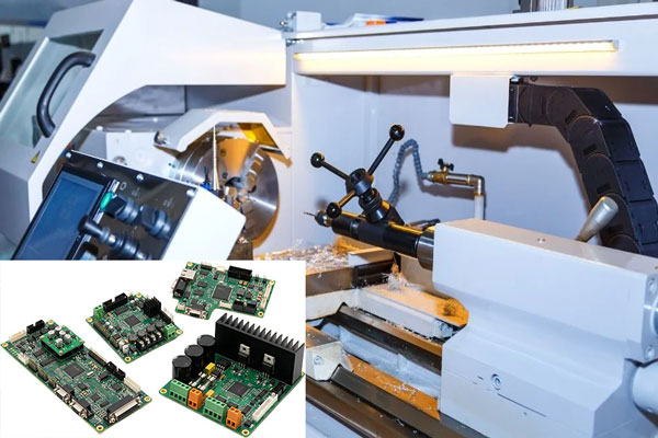
Prototype quantities are usually small, often a handful of boards or a few dozen. Setup work dominates the cost at this stage, so spreading it across a slightly larger lot is often sensible. Building enough boards for bench testing, environmental checks and a spare set avoids a second order for one missing sample. Buyers should plan the quantity around the test plan rather than around the minimum order. That approach usually costs less than a rushed repeat run later.
Cost control also comes from timing. Changing a design before fabrication costs an email. Changing it after fabrication costs new tooling, new materials and lost days. Engineers should settle the stackup, the component placement and the critical tolerances before releasing files. A design review at that point is cheap insurance. When the prototype passes, the volume order can proceed with fewer unknowns. A turnkey PCB assembly scope can then cover fabrication, sourcing and assembly under one schedule.
Moving From Prototype to Volume
The handover from prototype to production deserves its own review. Engineers should confirm that every change made during testing reached the final files. It is common for a prototype to carry a wire fix or a swapped component that never returns to the drawing. That gap causes failures at volume. A short comparison between the tested sample and the released documentation catches it. The production process sheet should also note any feature that needed special attention during the prototype build.
Repeat orders bring their own risks. Materials change, operators rotate and process parameters drift. Keeping the prototype records gives the factory a reference point for comparison. When a later lot shows a different result, the team can trace it back to a specific change rather than guessing. Buyers should ask how the factory handles engineering changes and how it confirms that a change was applied. Clear answers here usually indicate a supplier that will handle volume with the same discipline shown on the samples.
The practical takeaway is straightforward. Treat the prototype run as the engineering evidence for the whole project. Confirm the stackup and materials, review the layout for signal and thermal behavior, assemble with controlled processes, and test against a written plan. Keep the records with the design files so volume production starts from a known baseline. Buyers who ask these questions early get fewer surprises later, and engineers get data they can defend when the design review comes.