Smart Hardware Development: From Concept to a Manufacturable Product
A smart hardware product is a system, not a circuit board. The enclosure decides the antenna performance, the firmware decides the battery life, the certification body decides the schedule, and the component choices decide whether the product can be built at the target cost. Teams that treat smart hardware development as a sequence of separate outsourced tasks discover the dependencies late, when changes are expensive.
Why Smart Hardware Is a Multi-Discipline Problem
Consumer products are developed against four constraints at once. Cost is the first: the bill of materials has to land inside a range that the retail price can support, and every engineering decision moves that number. Power is the second: for anything battery powered, the average current draw defines the product experience, and it is a system property rather than a component property.
Connectivity is the third. Wi-Fi, Bluetooth, Zigbee, LoRa and cellular modules all impose their own layout rules, and the difference between a design that passes certification and one that fails is often a few millimetres of ground plane and the placement of a matching network.
Certification is the fourth. FCC, CE, UKCA and the regional variants test the finished product, and a design that ignores the requirements until after tooling has been cut will spend months and real money correcting something that could have been designed in. For consumer electronics design, the certification targets belong in the specification from day one.
The Disciplines That Must Agree
Hardware design sets the architecture, the power tree, the interfaces and the layout. Firmware development sets what the product actually does: the sleep behaviour, the user experience, the update mechanism and the way faults are handled. In products with a radio, RF engineering sets the matching, the antenna and the coexistence strategy. And the mechanical design sets the volume, the thermal path and the position of every connector and sensor.
The failures caused by separating these disciplines are predictable. A low-power design that cannot reach its target because the firmware never enters its deepest sleep state. An antenna that worked on the development board but not inside the enclosure. A battery that runs hot because the charging current was set before the thermal design existed. Coordinating hardware and firmware development in one team is the cheapest way to avoid the first and the most common of these problems.
Power Budget First, Components Second
For a battery-powered product, the power budget should be written before the schematic. It starts with the target: how long the product must run between charges, and how the user will actually use it. From there, the budget allocates average current to each subsystem: the radio, the sensors, the display, the processing and the quiescent losses of the regulators.
Only then does component selection make sense. A radio module with a lower transmit current may still consume more energy over a day if its idle current is higher. A sensor that samples continuously may cost more energy than the processor that reads it. And the quiescent current of a regulator that looked excellent at full load can dominate the average when the product spends 99 percent of its life asleep.
RF Layout: Where Products Quietly Fail
An RF layout is a set of constraints rather than a set of traces. The module manufacturer publishes a keep-out area, a recommended ground plane and a reference layout for the matching network, and those recommendations exist because the module was characterised with them.
The mistakes are consistent across projects: a ground plane cut underneath the antenna to make room for a battery, a matching network placed far from the pin it matches, a crystal routed next to a switching supply, a metal enclosure part that ends up inside the keep-out area after a mechanical change. Each one moves the resonance or raises the noise floor, and each one is inexpensive to avoid while the layout is still being edited.
It is also worth planning coexistence early. A product with Wi-Fi, Bluetooth and a cellular modem shares the spectrum with itself, and the arbitration strategy is a firmware and hardware decision rather than a certification problem to be solved later.
Design for Manufacturing Starts at the Schematic
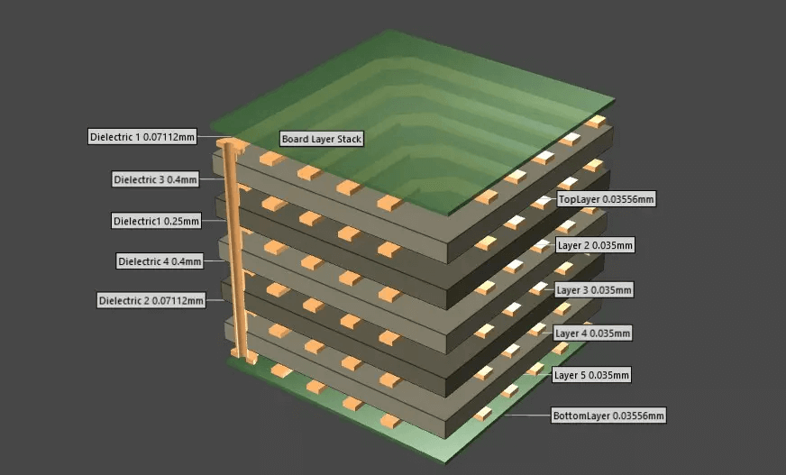
Design for manufacturing is not a review that happens after the layout is finished. It is a set of choices made throughout the design: package sizes that the assembly line can place reliably, component clearances that allow inspection, test points that let production verify the board, a panel design that suits the volume, and a bill of materials whose parts are actually available in the quantities the forecast requires.
The reward is a prototype that behaves like the production product. When the prototype is built with the same processes, the same stencils and the same test coverage as the volume build, the results transfer, and the gap between a working sample and a shipping product closes quickly.
Choosing a Development Partner
- Case studies in your category. A team that has shipped a wearable or a smart home device knows the pitfalls of that category, from enclosure tolerances to app connectivity.
- Coverage of the full stack. Hardware, firmware, RF and the manufacturing handover should belong to one team, or to a group of teams that work together routinely.
- A supply chain process. Components procurement should happen during design, with alternates qualified before the shortage.
- A working prototype path. Fast prototype PCB assembly with real inspection shortens each iteration, and iterations are how the product gets good.
- Clear ownership. Agree in writing who owns the source code, the design files, the tooling and the test fixtures.
From Prototype to Production
The transition from a working prototype to a production product is where most schedules slip. The design must be frozen, the test coverage must be defined, the fixtures must be built, and the process must be proven at the target volume. A partner who runs the production line as well as the design team will have started planning that transition during the layout, because the test plan and the panel design are part of it. It is not a coincidence that our process places the manufacturing review before the design is released: the earlier the factory sees the design, the cheaper the problems are.
FAQ
Can one company really cover hardware and firmware? A capable development partner will have both skills in house; where a specialist is needed, they should manage that subcontract rather than leaving it to the customer.
When should the mechanical design start? At the same time as the electronics. The enclosure constrains the antenna, the thermal path and the connector positions, so treating it as a later task creates rework.
How much does certification cost? It varies by market and radio configuration, but the dominating cost is often the schedule: a failed test means a re-test cycle, and a re-test cycle means a slip in the launch.
Is a module better than a chip-down radio? Modules reduce certification and RF risk at a higher unit cost. The right answer depends on volume and on how much engineering time the project can afford.
What should a customer prepare before approaching a development partner? A product definition, the expected volume, the target cost, the markets to be certified and the non-negotiable features. Everything else can be developed together.
Summary
Smart hardware development succeeds when the constraints are treated as one problem: cost, power, radio performance, certification and manufacturability, resolved by a team that owns hardware, firmware and the production handover. For a connected device, the assembly partner is part of that chain, and an Internet of Things PCBA supplier who understands the radio and the power budget will catch problems at layout review rather than at certification.