
Solder Sleeve Splices and Heat Shrink Termination Methods
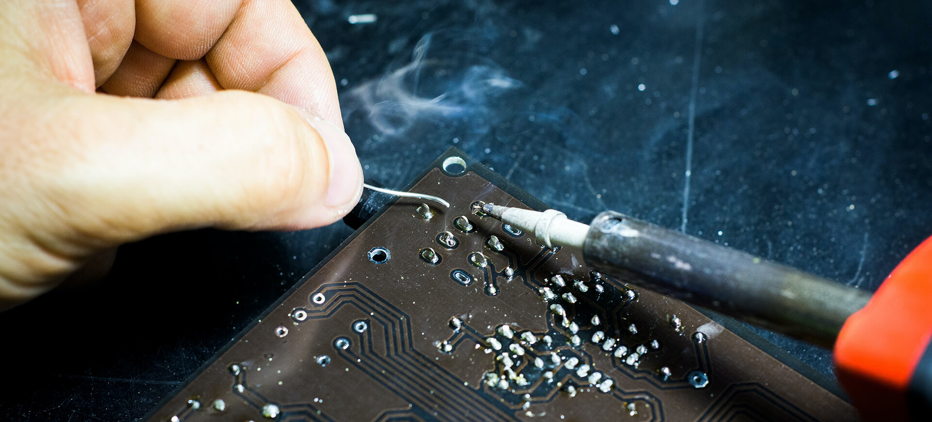
Where a wire has to be joined permanently and then survive vibration, moisture and repeated handling, a solder sleeve is often the most reliable answer. It combines a measured ring of solder, a thermoplastic sealing insert and a heat shrink outer tube in one part. Applying heat does three jobs at once: it melts the solder, melts the sealant and shrinks the sleeve onto the joint.
What a Solder Sleeve Does
A solder sleeve makes an insulated, environmentally sealed splice in a single operation. The solder ring is positioned over the conductor overlap, the sealing inserts sit either side of it, and the outer sleeve grips the wire insulation. The result is a joint that is electrically sound, mechanically supported and sealed against moisture ingress.
The alternative is to crimp or solder a splice and then cover it with separate tubing, which requires the operator to control three materials and two processes. A sleeve reduces that to one operation with one heat input, which is why it is common in harness work, sensor leads and any application where the joint must survive the field.
Construction and How It Works
The solder preform inside a sleeve is usually a flux cored ring sized to give the right volume for the conductor combination it is rated for. When the sleeve is heated the ring melts, the flux activates and the solder wicks around the strands. The sealing inserts melt at a lower temperature than the solder and flow to fill the space around the joint.
Because the solder is pre-measured, the joint does not depend on the operator feeding wire solder by hand. That removes the two most common causes of a weak splice, which are too little solder and enough heat to damage the insulation. The trade-off is that the sleeve must match the conductor size, and a mismatch cannot be corrected by technique.
Choosing the Right Sleeve Size
Sleeve size is specified by the wire gauge range it accepts and by the outside diameter it will shrink to. The joint must fit inside the sleeve before shrinking, with enough clearance for the solder ring and the sealing inserts to sit correctly. A sleeve that is too large will not seal against the insulation, and one that is too small will not close over the conductors.
The expanded inside diameter, the recovered inside diameter and the shrink ratio together define whether the sleeve will grip the insulation firmly. Where the two wires are different gauges, the recovered diameter must still seal the smaller one, which is a common source of leaks in mixed gauge splices. The manufacturer’s selection table is the starting point, not an estimate.
Heat Application and Shrink Control
Sleeves are applied with a hot air gun or a radiant heater, and the heat has to be applied evenly along the joint. Starting at one end and working along pushes the sealant ahead of the shrinking tube and produces a better seal than heating the centre first. The sleeve should be rotated so both sides see the same temperature.
The endpoint is visible: the solder melts and flows, the tubing shrinks and a small bead of sealant appears at each end. Continuing to heat after that point damages the insulation and can drive the sealant out of the joint. Open flame is generally avoided because it gives uneven heat and can scorch the sleeve and the wire.
Preparing the Conductor and Splice
Stranded conductors should be stripped to the length the sleeve specifies, with no nicked strands and no stray whiskers outside the joint. Oxidation and contamination have to be removed, because the flux in the ring has a limited capacity and cannot clean a heavily tarnished conductor. The two conductors should overlap or butt correctly for the sleeve type.
A lap joint, where the strands overlap, gives more solder contact area and is more tolerant of positioning than a butt joint. Where the conductor is a solid wire, the same principle applies but the solder ring volume is smaller. Surface condition is assessed the same way as for any soldered joint, using the methods described in this guide to solderability testing.
Crimp, Solder and Welded Alternatives
Crimping is faster and more repeatable than soldering for high volume harness work, and a correctly set crimp is a reliable joint. It is less suitable where the joint must be sealed, and a crimped splice still needs insulation and sealing applied afterwards. Where the strands are difficult to solder, such as aluminium, a mechanical splice is usually preferred.
Welding and ultrasonic bonding produce joints without solder and are used where the metals are incompatible with soldering or where a very low resistance is needed. Each method has a different failure signature, so the choice should come from the application requirements rather than from the equipment already on the bench.
Strain Relief and Mechanical Support
The sleeve provides some strain relief by gripping the insulation either side of the joint, but the amount depends on how much of the sleeve has shrunk onto the wire. Where a splice sits in a cable that will be flexed, additional support is needed so that bending is taken by the insulation rather than by the solder joint.
Support is normally provided by the geometry of the harness: a tie, a clip or a sleeve position that keeps the splice in a straight section rather than at a bend. The general approach to designing joints that tolerate movement is the same one used for component tolerance and reliability, where stress is moved away from the weakest feature.
Inspection, Testing and Acceptance
Inspection after shrinking is visual and dimensional. The solder should be visible as a smooth fillet in the transparent section of the sleeve, the sealant should form a continuous bead at both ends, and the tubing should be smooth without bubbles, charring or pinched areas. Any of those signs indicates a joint that should be rejected.
Electrical acceptance is usually a continuity and resistance check, with a pull test on a sample to confirm mechanical strength. Thermal cycling and moisture exposure are used where the joint will see a harsh environment, and the results are compared with the acceptance criteria written into the work instruction. Inspection that is not written down tends to drift, and the same principle applies to the joint defects catalogued in this guide to solder defects and board failures.
Process Control in Production
A solder sleeve process is controlled through the heat source, the fixture that holds the wire, and the operator’s visual criteria. The heater should have a set temperature and a defined dwell, and where a hot air tool with a hood is used, the hood size has to suit the sleeve so that heat is not applied to the wire beyond the joint.
Training matters more here than in many operations because the endpoint is judged by eye. A sample of sleeves should be cross-sectioned periodically to confirm that the solder has wetted the strands and that the sealant has flowed as intended. The wider approach to documenting and auditing such a step is the same one covered in the PCB production process flow for other assembly operations.
FAQ
How do I know when a solder sleeve is fully heated? The solder ring melts and flows along the joint, the tubing shrinks onto the wire, and a small bead of sealant appears at each end. Once that bead is visible and the solder fillet looks smooth, the joint is complete and further heat will only damage the insulation.
Can a solder sleeve be used on solid wire? Yes, provided the sleeve is rated for the conductor size and the solder volume suits a solid rather than a stranded conductor. Solid wire needs less solder, and using a sleeve intended for stranded wire can leave excess solder inside the joint or produce a stiff, overfilled splice.
What causes a leak in a sealed splice? Usually a size mismatch, either a sleeve too large for the insulation or one that cannot recover far enough onto a smaller conductor. Damaged insulation, a contaminated conductor that prevents wetting, and overheating that drives the sealant out of the joint are the other common causes.