What Is a PCB Connector? PCB Design, PCB Manufacturing & Connector Guide
Printed circuit boards (PCBs) are fundamental components in almost every modern electronic product. They provide the electrical and mechanical platform that connects integrated circuits, passive components, sensors, power devices, and other electronic elements.
However, not every electrical connection needs to be permanently soldered onto the PCB. When a PCB needs to connect to another circuit board, cable, wire harness, module, display, battery, or external device, a PCB connector can provide a practical and reliable interface.
So, what is a PCB connector?
A PCB connector is an electromechanical component designed to establish a removable or semi-permanent electrical connection between a PCB and another PCB, wire, cable, module, or external electrical system. Depending on its design, a connector can carry power, digital data, analog signals, high-speed signals, or combinations of these functions.
PCB connectors are therefore an important part of PCB Design, PCB Manufacturing, and PCB assembly. Selecting the correct connector affects electrical performance, mechanical reliability, assembly requirements, serviceability, and the overall size of the finished product.
From smartphones and computers to industrial equipment, automotive electronics, medical devices, and aerospace systems, connectors provide an essential interface between different parts of an electronic system.
What Is a PCB Connector?
A PCB connector is an interface component that provides electrical and mechanical connectivity between a printed circuit board and another electrical element.
Unlike a copper trace that permanently connects circuits within a PCB, a connector is typically designed to provide a separable interface. This allows boards, cables, modules, and other components to be connected and disconnected when required.
A typical connector system may consist of:
- A plug or male connector
- A receptacle or female connector
- Contacts or terminals
- A connector housing
- Mechanical locking or retention features
- Mounting structures
The actual structure varies significantly depending on the connector type and application.
For example, a board-to-board connector may connect two PCBs directly, while a wire-to-board connector connects a cable or wire harness to a PCB.
Connectors can carry:
- Power
- Ground
- Digital signals
- Analog signals
- High-speed data
- Control signals
- RF signals in specialized designs
Because the connector becomes part of the electrical path, its contact resistance, current rating, voltage rating, impedance characteristics, insertion loss, mechanical strength, and environmental specifications may all need to be considered during design.
For this reason, connector selection should be addressed during the early stages of PCB Design, rather than added only after the board layout is complete.
Types of PCB Connectors
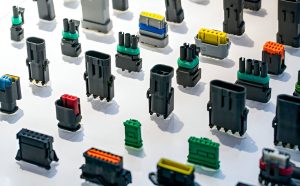
There is no single connector suitable for every PCB application. Different products require different connector structures based on electrical requirements, mechanical constraints, environmental conditions, mating cycles, signal speed, and available space.
PCB connectors can be categorized in several ways.
1. Based on Connection Method
One common classification divides connectors into three major categories:
Board-to-Wire Connectors
Board-to-wire connectors connect a PCB to individual wires or a cable assembly.
Common examples include:
- Wire-to-board terminal connectors
- Crimp connectors
- Insulation displacement connectors (IDC)
- Wire harness connectors
These connectors are widely used when the PCB needs to communicate with sensors, motors, batteries, switches, displays, or other external components.
Wire-to-Wire Connectors
Wire-to-wire connectors connect two wires or cable assemblies.
They are commonly used in cable harnesses and electrical systems where a detachable connection is desirable.
Board-to-Board Connectors
Board-to-board connectors directly connect two PCBs.
Common examples include:
- Pin headers
- Board-to-board receptacles
- Card-edge connectors
- Mezzanine connectors
- Stacking connectors
These connectors are particularly useful in modular electronic products where multiple circuit boards need to communicate with each other while occupying limited space.
2. Based on Application
PCB connectors can also be classified according to their intended applications.
USB Connectors
USB connectors are widely used for both data communication and power delivery.
Common USB form factors include:
- USB Type-A
- USB Type-B
- USB Type-C
- Micro-USB
USB Type-C is particularly common in modern electronic devices because of its compact form factor and support for high-speed data and power-delivery applications when implemented with the appropriate specifications.
Automotive Connectors
Automotive connectors must operate reliably under demanding environmental conditions.
Automotive electronic systems can experience:
- Vibration
- Mechanical shock
- Temperature cycling
- Humidity
- Dust and contaminants
- Electrical transients
Connectors used in automotive systems therefore need appropriate mechanical retention, environmental sealing where required, and electrical performance suitable for the application.
They can be found in applications such as:
- Vehicle sensors
- Infotainment systems
- Engine control systems
- Battery management systems
- Advanced driver-assistance systems
- Lighting systems
- Safety systems
Specialized automotive Ethernet interfaces, including Single Pair Ethernet (SPE) solutions, may also be used in suitable vehicle architectures.
Circular Connectors
Circular connectors are available in numerous sizes, contact configurations, and environmental ratings.
They are commonly used where mechanical robustness, secure mating, and resistance to demanding environments are important.
Applications can include:
- Industrial equipment
- Robotics
- Test equipment
- Transportation systems
- Outdoor electronics
- Aerospace systems
FFC/FPC Connectors
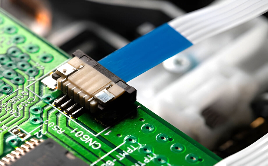
FFC and FPC connectors are designed to connect flexible flat cables or flexible printed circuits to PCBs.
They are widely used in compact electronic products such as:
- Smartphones
- Cameras
- Laptops
- Displays
- Printers
- Portable devices
Their low-profile design makes them valuable when PCB space and product thickness are tightly constrained.
Memory and Card Connectors
Memory and card connectors provide interfaces for removable storage or memory modules.
Examples include connectors designed for:
- Memory cards
- SIM cards
- Memory modules
- Expansion cards
Ethernet and Modular Connectors
Modular connectors are commonly used for network and communication interfaces.
RJ-style connectors, for example, are widely used in Ethernet networking applications, although the exact connector and physical interface depend on the networking standard and equipment design.
Audio and Video Connectors
PCB-mounted audio and video connectors can provide interfaces for external equipment.
Examples include:
- Audio jacks
- HDMI
- DisplayPort
- VGA
- RCA interfaces
The appropriate connector depends on the required signal type, bandwidth, mechanical design, and applicable interface specification.
Power Connectors
Power connectors are designed to deliver electrical power between the PCB and external equipment, batteries, adapters, or other power systems.
Important specifications include:
- Rated current
- Rated voltage
- Contact resistance
- Temperature rise
- Mating cycles
- Wire or PCB termination method
- Mechanical retention
High-current applications require particular attention to contact resistance and thermal performance.
Fiber-Optic Connectors
Fiber-optic connectors provide optical interfaces rather than conventional electrical signal paths.
They are used in applications involving high-speed communications, networking, telecommunications, and other systems where optical transmission is required.
Terminal Blocks
Terminal blocks provide convenient wire-to-PCB connections and are widely used in industrial and power-related equipment.
They are especially useful when field wiring needs to be connected, disconnected, or serviced efficiently.
Why Are PCB Connectors Used?
Understanding what a PCB connector is also requires understanding why engineers use connectors instead of permanent soldered connections.
Common applications include: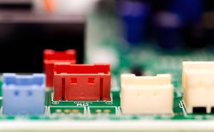
1. Power Delivery
Connectors can provide removable power connections between a PCB and a battery, power supply, motor, or external system.
2. Data Transmission
High-speed connectors can transmit digital data between PCBs, cables, modules, and external equipment.
3. Signal Transmission
Connectors can carry analog, digital, control, sensor, RF, or other electrical signals.
4. Display Connections
FFC/FPC connectors and other compact interfaces are commonly used to connect displays and control boards.
5. Networking
Network connectors allow PCBs to communicate with external networking equipment or communication systems.
6. Modular PCB Systems
Board-to-board connectors make it possible to divide a complex electronic system into multiple functional PCB modules.
7. Service and Maintenance
A detachable connector can make it easier to replace modules, cables, or subassemblies during servicing.
Advantages of Using PCB Connectors
PCB connectors provide several important benefits in electronic product design.
Easy Installation and Replacement
A connector can allow a module or cable to be disconnected without desoldering individual wires or components.
This can significantly simplify maintenance and product servicing.
Simplified Prototyping
Connectors can make prototype development more flexible by allowing boards, modules, and cables to be connected and disconnected during testing.
Modular Design
Board-to-board and wire-to-board connectors support modular product architectures.
A complex system can be divided into functional modules, making development, testing, servicing, and upgrades easier.
Space Optimization
Miniature connectors can provide high-density connections in compact electronic products.
This is particularly important for smartphones, wearables, portable medical devices, cameras, and other space-constrained applications.
Improved Assembly Flexibility
Depending on the connector design, PCB connectors can be installed using SMT, THT, press-fit, or other termination technologies.
The appropriate method should be selected according to the connector design and assembly process.
Reliable Mechanical Retention
Many connectors include locking mechanisms, latches, friction features, or other retention structures to prevent accidental disconnection.
For products exposed to vibration or shock, connector retention can be particularly important.
Important PCB Connector Selection Criteria
Choosing a connector should not be based solely on physical compatibility.
During PCB Design, engineers should evaluate several parameters.
Electrical Requirements
Consider:
- Voltage rating
- Current rating
- Contact resistance
- Number of contacts
- Signal type
- Signal frequency
- Differential-pair requirements
- Controlled impedance
- Crosstalk
- Insertion loss
High-speed applications require special attention to connector impedance, signal discontinuities, crosstalk, and insertion loss.
Mechanical Requirements
Mechanical considerations include:
- Available board space
- Connector height
- Mating direction
- Mounting method
- Retention mechanism
- Mating cycles
- Required insertion and extraction force
The connector must also fit the product enclosure and align correctly with external interfaces.
Environmental Requirements
For industrial, automotive, outdoor, or aerospace applications, environmental conditions can be critical.
Consider:
- Operating temperature
- Humidity
- Vibration
- Shock
- Dust
- Corrosive environments
- Water or splash exposure
- Chemical exposure
A connector should be selected according to the actual environmental requirements rather than simply choosing a general-purpose connector.
Manufacturing Requirements
Connector selection also affects PCB Manufacturing and assembly.
Engineers should confirm:
- SMT or THT compatibility
- Recommended pad design
- Hole dimensions
- Component keepout requirements
- Reflow compatibility
- Selective soldering requirements
- Assembly orientation
- Inspection accessibility
Large connectors can also introduce mechanical stress during assembly and repeated mating.
PCB Connector Design Considerations
A connector should be incorporated into the PCB design from the beginning.
The PCB footprint must accurately match the manufacturer’s recommended land pattern and mechanical dimensions.
Designers should verify:
- Contact pitch
- Pad dimensions
- Plated-hole dimensions
- Connector outline
- Courtyard
- Keepout areas
- Mechanical mounting points
- Pin numbering
- Polarization features
- Mating direction
For high-speed connectors, the PCB routing around the connector is equally important.
Avoiding unnecessary stubs, maintaining appropriate reference planes, controlling impedance, and minimizing discontinuities can help maintain signal integrity.
For high-current connectors, copper thickness, pad geometry, via capacity, thermal management, and current distribution should also be considered.
Common PCB Connector Problems
Incorrect connector selection or poor implementation can create several problems.
Signal Loss
A connector introduces an electrical transition into the signal path. Poor connector selection or layout can increase insertion loss and signal degradation.
Contact Resistance
Higher contact resistance can result in voltage drop and heat generation, particularly in higher-current applications.
Mechanical Failure
Repeated mating, vibration, shock, or excessive insertion force can damage contacts or locking mechanisms.
Misalignment
Poor mechanical design can make mating difficult or cause excessive stress on the PCB.
Corrosion
Environmental exposure can affect connector contacts and increase contact resistance.
Appropriate contact materials, plating, sealing, and environmental protection should therefore be selected according to the application.
Manufacturing Defects
Incorrect footprints, insufficient solder coverage, poor alignment, or inappropriate soldering processes can result in unreliable connector attachment.
How Kingda Supports PCB and PCBA Projects
Selecting the right PCB manufacturing and assembly partner is important when a product includes complex connector interfaces.
Kingda provides integrated PCB and PCBA services covering PCB fabrication, component sourcing, SMT assembly, THT assembly, inspection, and testing.
For projects involving board-to-board connectors, FFC/FPC interfaces, high-density components, power connectors, or other specialized interconnection structures, early design and manufacturing review can help identify potential footprint, clearance, assembly, and reliability issues.
By considering connector requirements during PCB Design and validating them before PCB Manufacturing, engineering teams can reduce redesign risks and improve overall product reliability.
Conclusion
So, what is a PCB connector?
A PCB connector is an electromechanical interface that provides a reliable connection between a PCB and another PCB, wire, cable, module, or external system. Unlike permanent soldered connections, connectors can provide detachable interfaces that simplify assembly, maintenance, modular design, and product upgrades.
PCB connectors are available in many forms, including board-to-board, board-to-wire, wire-to-wire, USB, FFC/FPC, card-edge, power, circular, Ethernet, audio/video, and specialized automotive and industrial connectors.
The correct connector depends on the electrical, mechanical, environmental, and manufacturing requirements of the application. During PCB Design, engineers should evaluate current and voltage ratings, signal integrity, connector dimensions, mating cycles, mechanical retention, environmental conditions, PCB footprint, and assembly compatibility.
Ultimately, choosing and implementing the right connector is an important part of both PCB Design and PCB Manufacturing. A well-selected connector can improve serviceability, modularity, reliability, and overall product performance, while an unsuitable connector can introduce signal integrity, thermal, mechanical, or manufacturing problems.
Article Summary
A PCB connector is an electromechanical interface used to connect a printed circuit board with another PCB, cable, wire, module, or external device. This guide explains the major types of PCB connectors, including board-to-board, board-to-wire, FFC/FPC, USB, automotive, power, circular, Ethernet, and other specialized connectors. It also covers connector applications, advantages, selection criteria, design considerations, common problems, and the relationship between connector selection, PCB Design, and PCB Manufacturing.