What Is a PCB Connector? PCB Design, PCB Manufacturing & Connector Types Guide
A printed circuit board (PCB) is one of the fundamental building blocks of modern electronic equipment. It provides the physical and electrical infrastructure needed to connect electronic components through conductive traces, pads, vias, and other interconnection structures.
However, not every electrical connection is made directly through PCB traces. Many electronic products need to connect one PCB to another PCB, a cable, a wire harness, a display, a battery, or an external device. This is where a PCB Connector becomes essential.
A PCB connector is an electromechanical component designed to establish a reliable electrical and mechanical connection between a PCB and another circuit, cable, wire, or PCB. Depending on its design, a connector can carry power, high-speed data, analog signals, control signals, or a combination of these functions.
For engineers working on PCB Design, understanding connector types, electrical specifications, mechanical requirements, and mounting methods is important because connector selection directly affects board layout, signal integrity, manufacturability, serviceability, and overall product reliability.
What Is a PCB Connector?
A PCB Connector is an electromechanical interface used to establish a detachable or semi-permanent electrical connection between a printed circuit board and another electrical system.
Unlike a copper trace, which permanently connects two points within a PCB, a connector provides an interface that can normally be mated and unmated. This makes connectors particularly useful when a PCB needs to communicate with another board, cable, module, peripheral, or replaceable subsystem.
PCB connectors can be used to transmit:
- Electrical power
- Digital data
- High-speed signals
- Analog signals
- Control signals
- Audio and video signals
A typical connector system consists of mating components. For example, a pin header may mate with a socket or receptacle. Depending on the application, the connector may also include contacts, housings, locking mechanisms, polarization features, and strain-relief structures.
Common examples include USB connectors, board-to-board connectors, card-edge connectors, wire-to-board connectors, terminal blocks, FFC/FPC connectors, and modular Ethernet connectors.
Why Are PCB Connectors Important?
PCB connectors provide a standardized interface between different parts of an electronic system. Instead of permanently soldering every external wire or module to the PCB, designers can use a connector to make the interface easier to assemble, test, replace, and maintain.
For example, a laptop may use connectors to connect its motherboard with the display, storage devices, keyboard, battery, speakers, and other modules. Similarly, industrial control equipment may use terminal blocks or specialized connectors to interface the PCB with external sensors and power systems.
For this reason, connector selection should be considered early in the PCB Design Process, rather than added after the board layout has been completed.
Types of PCB Connectors
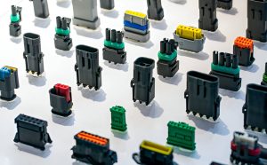
There are many types of PCB connectors, and no single connector is suitable for every application. The appropriate design depends on factors such as current, voltage, signal frequency, mating cycles, available space, environmental conditions, mechanical stress, and required reliability.
PCB connectors can be classified in several ways.
1. PCB Connectors by Connection Method
One common classification is based on what the connector connects.
Wire-to-Board Connectors
Wire-to-board connectors connect individual wires or cable assemblies to a PCB.
Typical examples include:
- Terminal blocks
- Crimp connectors
- Insulation displacement connectors (IDC)
- Wire harness connectors
These connectors are commonly used for power connections, sensors, control systems, industrial equipment, and other applications where external wiring must interface with a PCB.
Wire-to-Wire Connectors
Wire-to-wire connectors connect two cables or wire assemblies rather than directly connecting two PCBs.
Depending on the application, these connectors may be used in power systems, data cables, internal wiring harnesses, and consumer electronics.
Board-to-Board Connectors
Board-to-board connectors establish electrical connections between two PCBs without requiring a separate cable.
Common examples include:
- Board-to-board mezzanine connectors
- Card-edge connectors
- Stackable headers
- Backplane connectors
Board-to-board connectors are particularly useful in modular electronic products because they allow multiple PCBs to be assembled into a compact system.
2. PCB Connectors by Application
Connectors can also be categorized according to their intended application.
USB Connectors
USB connectors are widely used for both power delivery and data communication. USB connector families include USB Type-A, Type-B, Type-C, and Micro-USB.
USB Type-C has become particularly common in modern electronics because it supports a reversible mating interface and can be used for multiple functions depending on the implementation, including data transfer, charging, and alternate signal modes.
When incorporating a USB connector into PCB Design, engineers need to consider differential-pair routing, impedance control, connector placement, power delivery requirements, ESD protection, and mechanical clearance.
Automotive PCB Connectors
Automotive electronics operate in demanding environments characterized by vibration, temperature fluctuations, moisture, electrical transients, and limited installation space.
Automotive connectors therefore require appropriate mechanical retention, environmental protection, contact reliability, and electrical performance.
Depending on the system, automotive PCB connectors can be used for sensors, control modules, infotainment systems, lighting, power electronics, and communication networks.
For high-speed automotive communication, specialized interfaces such as automotive Ethernet connectors may be used. The exact connector specification depends on the communication standard and vehicle architecture.
Circular Connectors
Circular connectors are available in various sizes, contact configurations, and environmental ratings.
Their mechanical structure can provide strong retention and resistance to vibration, making them useful in industrial equipment, instrumentation, outdoor systems, transportation equipment, and other demanding applications.
Other Common PCB Connector Types
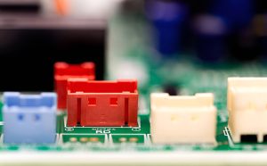
In addition to the connector categories above, many specialized connectors are used in electronic products.
FFC and FPC Connectors
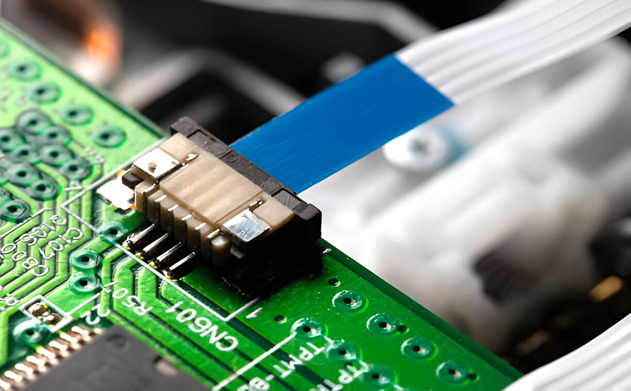
FFC (Flexible Flat Cable) and FPC (Flexible Printed Circuit) connectors provide compact connections between flexible cables or flexible circuits and PCBs.
They are commonly found in:
- Smartphones
- Laptops
- Displays
- Cameras
- Printers
- Consumer electronics
- Compact embedded systems
Their low-profile structure makes them particularly useful where PCB space is limited.
Memory and Card Connectors
Memory and card connectors provide removable interfaces for memory cards, expansion cards, and other plug-in modules.
Card-edge connectors are another common solution for connecting a PCB directly to a corresponding socket or slot.
Modular and Ethernet Connectors
Modular connectors, including common Ethernet interfaces, are frequently used in networking equipment, computers, industrial controllers, and communication devices.
When designing high-speed interfaces, the connector itself becomes part of the signal path. Therefore, connector characteristics such as impedance, insertion loss, return loss, crosstalk, and contact geometry may need to be considered.
Audio and Video Connectors
Audio and video connectors provide interfaces for transmitting multimedia signals.
Examples include:
- HDMI connectors
- DisplayPort connectors
- VGA connectors
- RCA connectors
- Audio jack connectors
The appropriate connector depends on the required signal format, bandwidth, mechanical design, and application.
Power Connectors
Power connectors are designed to safely deliver electrical power between the PCB and an external power source or subsystem.
Engineers need to consider rated voltage, rated current, contact resistance, temperature rise, creepage and clearance, mechanical retention, and the expected mating environment.
Terminal Blocks
Terminal blocks provide a practical interface for connecting external wires to a PCB.
They are particularly common in industrial control systems, power supplies, automation equipment, instrumentation, and other products that require convenient field wiring.
What Are PCB Connectors Used For?
The primary purpose of a PCB Connector is to create a reliable electrical and mechanical interface between different parts of an electronic system.
Typical applications include:
- Connecting displays and LED modules
- Transmitting digital data
- Connecting memory or expansion modules
- Transmitting high-speed signals
- Supplying electrical power
- Connecting networking equipment
- Connecting sensors and actuators
- Connecting external cables and wire harnesses
- Linking multiple PCBs within a system
- Supporting replaceable or serviceable modules
Some connectors are designed to carry several types of signals simultaneously. For example, a single connector may provide power, communication signals, and control lines within the same interface.
Advantages of Using PCB Connectors
PCB connectors provide several practical benefits during product development and manufacturing.
Easier Assembly and Maintenance
A detachable connector allows modules and cables to be connected without permanently soldering every external connection. This can simplify assembly, troubleshooting, repair, and replacement.
Simplified Prototyping
Connectors can make prototypes easier to assemble and modify. Engineers can disconnect modules during testing without repeatedly soldering and desoldering wires.
Modular Product Architecture
Board-to-board and cable connectors allow a complex electronic product to be divided into multiple functional modules.
This modular architecture can simplify system development and make future modifications easier.
Space Savings
Modern connectors are available in very compact packages. Low-profile and fine-pitch connector designs can help engineers achieve high-density product architectures where PCB space is limited.
Reliable Electrical Connections
A properly selected connector provides controlled contact geometry and mechanical retention, helping maintain consistent electrical connections over the expected service life.
However, reliability depends on selecting a connector that matches the electrical, mechanical, environmental, and mating requirements of the application.
Important Factors When Selecting a PCB Connector
Choosing a connector based only on its physical dimensions can create problems during PCB Manufacturing and product operation.
Engineers should evaluate several parameters before selecting a connector.
Electrical Requirements
Important electrical specifications may include:
- Rated voltage
- Rated current
- Contact resistance
- Insulation resistance
- Dielectric withstand voltage
- Signal frequency
- Controlled impedance requirements
For high-speed interfaces, signal-integrity characteristics become particularly important.
Mechanical Requirements
The connector should fit the available board and enclosure space.
Engineers should consider:
- Connector dimensions
- Mounting method
- Mating direction
- Insertion and extraction force
- Mating cycle requirements
- Mechanical retention
- Vibration resistance
- Keying and polarization
Environmental Requirements
Connectors used in industrial, automotive, aerospace, or outdoor applications may need to withstand:
- High and low temperatures
- Humidity
- Dust
- Vibration
- Shock
- Corrosive environments
- Moisture exposure
The required environmental protection depends on where and how the final product will operate.
PCB Connector Considerations in PCB Design
Connector selection has a direct impact on PCB Layout.
Before finalizing the board design, engineers should reserve adequate space around the connector for installation, mating, cable routing, and mechanical clearance.
The PCB footprint should be created according to the connector manufacturer’s recommended land pattern and mechanical drawing. Engineers should also verify the connector’s pin numbering and orientation carefully.
For high-speed connectors, routing should be planned from the beginning. Differential pairs may require controlled impedance, matched routing strategies, short signal paths, and appropriate reference planes.
Power connectors require additional attention to current capacity, copper width, thermal performance, and voltage drop.
Mechanical CAD data can also be used to verify that the connector fits correctly within the product enclosure.
PCB Manufacturing and Assembly Considerations
Connector design also affects PCB Manufacturing and assembly processes.
Depending on the connector type, installation may involve:
- SMT placement
- Through-hole insertion
- Reflow soldering
- Wave soldering
- Selective soldering
- Press-fit assembly
- Manual assembly
Some connectors combine SMT and through-hole mounting features to provide both electrical connections and mechanical reinforcement.
Before production, the PCB manufacturer and assembly provider should review the connector footprint, hole dimensions, soldering requirements, component clearances, and assembly sequence.
This helps prevent problems such as insufficient soldering, connector misalignment, interference with nearby components, or mechanical conflicts.
Common PCB Connector Problems
Even a high-quality connector can cause system problems if it is incorrectly selected or improperly integrated into the PCB.
Common issues include:
- Incorrect pin assignment
- Reversed connector orientation
- Poor solder joints
- Insufficient mechanical retention
- Contact oxidation
- Excessive contact resistance
- Signal loss
- Crosstalk
- Impedance discontinuities
- Connector damage from excessive mating force
- Insufficient clearance around the connector
For high-speed applications, a connector should be treated as part of the complete signal path rather than as an isolated mechanical component.
Conclusion
A PCB Connector is an important electromechanical interface that allows PCBs to communicate with other boards, cables, modules, power sources, and external equipment. Connector types range from wire-to-board and board-to-board connectors to USB, FPC/FFC, card-edge, Ethernet, power, terminal-block, and specialized industrial connectors.
The correct connector must be selected according to electrical, mechanical, environmental, and signal-integrity requirements. Connector selection should also be incorporated into the early stages of PCB Design so that footprints, routing, mechanical clearance, power distribution, and assembly requirements can be considered together.
From PCB Manufacturing through final assembly and testing, accurate connector placement and reliable soldering or mechanical attachment are essential. By selecting the appropriate connector and integrating it correctly into the PCB layout and manufacturing process, engineers can create electronic products that are easier to assemble, maintain, test, and operate reliably.