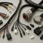
At first glance, a wiring harness may appear to be nothing more than an organized bundle of wires with connectors attached at the ends. In professional engineering and manufacturing, however, a wire harness is a highly engineered electrical assembly. The selection and integration of every component—from the conductor and insulation to the connector, terminal, shielding, and protective covering—can directly affect electrical performance, mechanical durability, safety, and service life.
Modern electrical systems are becoming increasingly compact, connected, and power-intensive. Wiring harness assemblies are now widely used in automotive systems, medical equipment, industrial automation, telecommunications, consumer electronics, robotics, energy systems, and other electronic products. They transmit electrical power, carry control signals, transfer data, and connect different functional modules within a complete system.
For engineers, selecting the right wiring harness components is therefore an important part of product development. An inappropriate wire gauge can cause excessive voltage drop or overheating. A poorly matched terminal can lead to unstable electrical contact. Inadequate sealing can allow moisture to enter the connector, while insufficient shielding can introduce electromagnetic interference (EMI).
As an experienced PCB manufacturer and PCB assembly service provider, Kingda also understands the importance of reliable interconnect solutions in complete electronic systems. By combining PCB prototype manufacturing, quick-turn PCB prototyping, and PCB assembly solutions, Kingda can support customers from initial design validation through production while considering the interfaces between PCBs, connectors, cables, and wiring assemblies.
What Is a Wiring Harness?
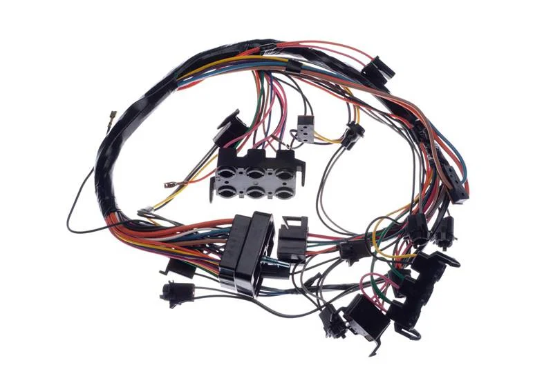
A wiring harness is an organized assembly of wires, cables, terminals, connectors, protective materials, and mounting accessories designed to transmit electrical power or signals between different components of an electrical system.
Instead of installing individual loose wires separately, engineers bundle and route them into a structured assembly. This makes installation more efficient and helps control wire routing, mechanical protection, identification, and electrical connectivity.
A typical wire harness assembly may include:
- Conductors and wires for transmitting electrical power or signals
- Terminals and crimp contacts for establishing electrical connections
- Connectors for detachable interfaces between systems
- Insulation and protective jackets for electrical and environmental protection
- Sleeves and conduits for abrasion and mechanical protection
- Tapes and wraps for bundling and vibration control
- Grommets and seals for pass-through protection and environmental sealing
- Clips, clamps, and brackets for mechanical mounting
- Shielding materials for EMI and signal-integrity control
- Labels and identification systems for assembly and traceability
A well-designed harness functions as an organized interconnection system rather than simply a collection of wires.
What Components Make Up a Wiring Harness?
The reliability of a wiring harness assembly depends on how its individual components work together. The main components can be divided into electrical, protective, and mechanical categories.
1. Conductors and Wires
The conductor is the primary electrical path within a wire harness. Copper is widely used because of its excellent electrical conductivity and flexibility, while tinned copper can provide additional resistance to oxidation and corrosion.
Engineers typically select wires according to:
- Current-carrying capacity
- Voltage rating
- Wire gauge
- Conductor construction
- Temperature range
- Flexibility and flex-cycle requirements
- Insulation material
- Signal characteristics
Common conductor constructions include stranded and solid-core wires. Stranded conductors are particularly useful when flexibility and resistance to repeated movement are important.
For signal applications, engineers may use twisted-pair cables, coaxial cables, or other specialized constructions to improve noise immunity and signal integrity.
2. Wire Insulation
Insulation surrounds the conductor and prevents unintended electrical contact while protecting the wire from environmental conditions.
Common insulation materials include:
- PVC
- XLPE
- TPE
- Silicone
- FEP
- PTFE
Material selection depends on the operating environment. For example, industrial equipment may require resistance to oil and chemicals, while automotive applications may require improved temperature and vibration resistance.
The correct insulation should be evaluated according to:
- Temperature resistance
- Flame resistance
- Chemical resistance
- Oil resistance
- UV resistance
- Flexibility
- Abrasion resistance
- Environmental requirements
3. Terminals and Crimp Contacts
Terminals and crimp contacts form the electrical and mechanical interface between the conductor and connector.
Typical examples include:
- Blade terminals
- Ring terminals
- Fork terminals
- Male and female crimp contacts
- Pin terminals
- Coaxial contacts
- High-current terminals
Crimp quality is critical to wire harness reliability. An improperly crimped terminal can result in increased contact resistance, intermittent connections, conductor pull-out, or excessive localized heating.
Professional harness manufacturing therefore requires appropriate crimp tooling and process control. Depending on the application, manufacturers may use crimp-height inspection, pull-force testing, visual inspection, and cross-sectional analysis to verify crimp quality.
4. Connectors
Connectors provide detachable electrical interfaces between the harness and other components such as PCBs, sensors, motors, controllers, power supplies, and equipment modules.
Important connector parameters include:
- Number of contacts
- Contact pitch
- Current rating
- Voltage rating
- Mating configuration
- Locking mechanism
- Keying orientation
- Environmental protection
- Mating-cycle requirements
- Terminal plating
- Connector size
Depending on the application, a custom wiring harness may use standard board-to-wire connectors, waterproof connectors, circular connectors, automotive connectors, high-current connectors, or RF connectors.
Connector selection must always be matched to the electrical, mechanical, and environmental requirements of the final product.
Protective Components Used in Wiring Harnesses
Electrical performance is only one part of harness reliability. Protective components help the assembly withstand vibration, abrasion, moisture, temperature changes, and mechanical stress.
Sleeves, Tubing, and Conduits
Common protection options include:
- PET braided sleeving for abrasion protection and flexible routing
- Heat-shrink tubing for insulation and strain relief
- Nylon conduit for mechanical protection
- PVC tubing for general-purpose applications
- Silicone tubing for higher-temperature environments
- Protective spiral wrap for flexible routing
The correct covering depends on the installation environment and required mechanical protection.
Tapes and Wrapping Materials
Tapes can be used to bundle wires, suppress vibration noise, improve abrasion resistance, and organize harness routing.
Examples include:
- Fabric tape
- Fleece tape
- PVC electrical tape
- Foam tape
- Aluminum shielding tape
- Specialized automotive harness tape
The tape material should be selected according to temperature, abrasion, noise, chemical, and environmental requirements.
Grommets and Seals
Grommets protect wires where a harness passes through a metal or plastic panel. They prevent sharp edges from damaging insulation and can also provide strain relief.
For applications exposed to water or dust, sealing components can be integrated around connectors and cable entries to achieve the required environmental protection level.
Clips, Clamps, and Brackets
Mechanical mounting components keep the harness in its intended position.
They help:
- Maintain the designed routing path
- Prevent excessive movement
- Reduce vibration
- Protect against abrasion
- Simplify installation
- Maintain appropriate clearance from heat sources and moving parts
For automotive and industrial systems, correct routing and mounting are especially important because harnesses may be exposed to continuous vibration and mechanical movement.
EMI Shielding for Wiring Harnesses
For sensitive electrical and communication systems, EMI shielding can be an essential part of the harness design.
Shielding may use:
- Aluminum foil
- Copper braid
- Tinned copper braid
- Foil-and-braid combinations
- Shielded connector assemblies
Shielding helps reduce the impact of external electromagnetic interference and can also reduce unwanted coupling between adjacent circuits.
For RF and high-speed applications, engineers must consider more than simply adding a shield. Cable construction, connector design, grounding strategy, impedance, routing, and termination all influence signal integrity.
For example, coaxial assemblies are commonly designed around controlled impedance such as 50 Ω or 75 Ω, depending on the application.
Labels and Identification Systems
Identification is an important part of a professional wire harness assembly.
Labels can include:
- Wire numbers
- Connector identification
- Pin information
- Assembly part numbers
- Serial numbers
- Barcodes
- QR codes
- Revision information
Clear identification reduces installation errors and makes troubleshooting and maintenance easier.
For OEM production, traceability can also connect a harness to its drawing revision, material information, production batch, and test records.
Why Use a Wiring Harness Instead of Loose Wires?
Using a structured wiring harness provides several practical advantages.
1. Better Organization
Bundling wires into a defined assembly makes complex electrical systems easier to install, inspect, and maintain.
2. Improved Mechanical Protection
Sleeves, tapes, conduits, clips, and strain-relief structures can protect conductors from vibration, abrasion, pulling, and repeated movement.
3. More Consistent Manufacturing
A standardized harness can be manufactured and tested as a complete assembly, reducing variations associated with manually routing individual wires during final equipment assembly.
4. Simplified Installation
Instead of installing dozens of individual wires, technicians can install one preassembled harness with defined connectors and mounting points.
5. Better Space Management
A properly designed harness provides controlled routing through tight equipment spaces and helps maintain clearance from heat sources, moving components, and sensitive circuits.
6. Easier Inspection and Testing
A complete harness can undergo continuity, insulation, hipot, pin-out, and functional testing before shipment to the final assembly line.
How Do Engineers Choose the Right Wiring Harness Components?
Selecting wire harness components requires more than matching connector types. Engineers should evaluate the complete operating environment.
1. Voltage and Current
The expected current determines the conductor size and thermal design.
Important considerations include:
- Continuous current
- Peak current
- Voltage
- Allowable voltage drop
- Ambient temperature
- Bundling conditions
- Cable length
For longer harnesses, voltage drop can become an important design consideration. Increasing conductor size may reduce electrical resistance and heat generation, but the final choice should be based on actual load and installation conditions.
2. Temperature
Temperature affects both conductor capacity and insulation life.
Engineers should evaluate:
- Normal operating temperature
- Maximum temperature
- Minimum temperature
- Temperature cycling
- Heat exposure from nearby components
Automotive engine compartments, industrial machinery, and power systems may require specialized high-temperature wire constructions.
3. Environmental Conditions
Consider whether the harness will encounter:
- Moisture
- Water
- Oil
- Chemicals
- Salt spray
- UV exposure
- Dust
- Abrasion
- Vibration
These factors influence the selection of insulation, connectors, seals, sleeves, and protective coverings.
4. Mechanical Movement
Harnesses installed in moving equipment require careful consideration of flex life.
Applications such as:
- Robotic arms
- Automated machinery
- Moving stages
- Hinged equipment
- Cable carriers
may require fine-stranded conductors, flexible insulation, controlled bend radii, and dedicated strain-relief structures.
5. Signal Integrity and EMI
For sensitive signals, engineers may need:
- Twisted pairs
- Coaxial cables
- Shielded cables
- Controlled impedance
- Proper grounding
- Appropriate connector systems
These considerations are particularly important for RF, communication, sensor, and high-speed digital applications.
6. Connector Compatibility
Connector selection must account for:
- Pin count
- Contact arrangement
- Pitch
- Keying
- Locking mechanism
- Mating direction
- Current rating
- Voltage rating
- Environmental requirements
The terminal must also be compatible with the selected conductor and connector housing.
7. Regulatory and Material Requirements
Depending on the target market, the harness may need to satisfy customer-specific or industry-specific material and compliance requirements.
Common considerations include:
- RoHS
- REACH
- UL-recognized or UL-listed components where applicable
- Halogen-free requirements
- Flame-retardant requirements
- Application-specific automotive, medical, aerospace, or industrial standards
Compliance should be verified against the specific product, market, and applicable standard rather than assumed from the component category alone.
Wiring Harness Design and Pre-Production Process
A reliable custom wire harness starts with a well-controlled engineering process.
Step 1: Requirements Analysis
The design team identifies:
- Electrical requirements
- Mechanical dimensions
- Operating environment
- Signal requirements
- Connector interfaces
- Installation method
- Regulatory requirements
- Expected production volume
Step 2: Electrical Schematic and Wire List
The schematic defines how each circuit is connected.
The wire list typically specifies:
- Wire part number
- Wire gauge
- Wire color
- Circuit function
- Terminal type
- Connector cavity
- Cut length
- Special requirements
Step 3: 2D and 3D Harness Design
For complex products, 3D wiring harness design can help engineers verify:
- Routing paths
- Bend radius
- Connector accessibility
- Mounting locations
- Clearance
- Interference
- Serviceability
This is particularly useful for automotive, robotics, industrial equipment, and other space-constrained systems.
Step 4: Material Selection
Engineers select compatible:
- Wires
- Terminals
- Connectors
- Insulation
- Sleeves
- Seals
- Tapes
- Shielding
- Mounting accessories
Step 5: Prototype Manufacturing
A wire harness prototype allows engineers to verify the design before committing to larger production quantities.
Prototype evaluation may include:
- Dimensional verification
- Connector compatibility
- Pin-out verification
- Continuity testing
- Mechanical fit
- Electrical performance
- Environmental testing where required
Step 6: Documentation and Revision Control
A professional harness project should maintain controlled documentation such as:
- Assembly drawings
- Wire lists
- BOM
- Connector specifications
- Crimp specifications
- Test requirements
- Revision history
- Inspection criteria
Good revision control is particularly important when the harness is integrated with a PCB or complete electronic assembly.
Wiring Harness Manufacturing Process
The wire harness manufacturing process typically consists of several controlled operations.
1. Wire Cutting
Wires are cut to the specified length according to the approved drawing and wire list.
Cut-length accuracy is important because excessive length can create routing problems, while insufficient length can place mechanical stress on terminals and connectors.
2. Wire Stripping
The insulation is removed from the specified portion of the wire without damaging the conductor strands.
3. Terminal Crimping
The appropriate terminal is crimped onto the prepared conductor using compatible tooling.
Depending on the application, manufacturers may verify:
- Crimp height
- Pull force
- Terminal position
- Conductor insertion
- Visual crimp quality
4. Connector Assembly
Crimped contacts are inserted into the correct connector cavities according to the approved pin-out.
Key checks include:
- Pin position
- Connector orientation
- Terminal locking
- Seal installation
- Keying configuration
5. Harness Bundling
Individual wires and subassemblies are arranged according to the required routing configuration.
Protection may then be added using:
- Sleeves
- Tapes
- Conduits
- Heat-shrink tubing
- Clips
- Grommets
- Strain relief
6. Labeling
The finished harness is identified using the appropriate part number, wire markings, connector identification, barcode, or other traceability information.
7. Electrical and Visual Inspection
Before shipment, the finished wire harness assembly should be inspected for:
- Correct wire routing
- Correct connector orientation
- Missing components
- Damaged insulation
- Incorrect pin-outs
- Crimp defects
- Labeling errors
Wiring Harness Testing
Testing is essential for confirming electrical connectivity and manufacturing consistency.
Continuity Testing
A continuity test verifies that the intended electrical paths are connected and identifies open circuits or incorrect connections.
Pin-Out Testing
Pin-out testing confirms that every conductor terminates at the correct connector cavity.
This is especially important for multi-pin harnesses where a single miswired circuit can prevent an entire system from operating correctly.
Insulation Resistance Testing
Insulation resistance testing checks the electrical isolation between conductors and other relevant conductive structures.
Dielectric Withstand Testing
Where required by the application, a high-voltage or hipot test can verify that insulation withstands the specified test voltage without unacceptable breakdown.
Functional Testing
For more complex assemblies, the harness can be connected to representative equipment or test fixtures to verify actual system functionality.
Environmental Testing
Depending on the application, testing may include:
- Temperature cycling
- Humidity exposure
- Vibration
- Mechanical flexing
- Water ingress
- Salt spray
- Chemical exposure
The exact test conditions should be defined according to the product specification and applicable standards.
Wiring Harness vs. Cable Assembly
Although wiring harnesses and cable assemblies are related, they are not always interchangeable terms.
Wiring Harness
A wiring harness generally consists of multiple individual wires or cables organized into a structured assembly. It may include numerous connectors, branches, terminals, clips, labels, and protective components.
It is commonly used where many circuits must be routed between multiple system components.
Cable Assembly
A cable assembly typically consists of one or more conductors enclosed within a common jacket or specialized cable construction and terminated with connectors.
Cable assemblies are often used for:
- Power connections
- Data transmission
- RF connections
- Audio/video interfaces
- Point-to-point communication
The appropriate solution depends on the electrical architecture, signal requirements, installation environment, and mechanical constraints.
Wiring Harness Applications by Industry
Automotive Wiring Harnesses
Automotive systems use extensive harness networks for:
- Engine control
- Sensors
- Lighting
- Infotainment
- ADAS
- Body electronics
- Battery systems
- Electric powertrain systems
Automotive harnesses may require high-temperature insulation, vibration resistance, sealed connectors, abrasion protection, and carefully controlled routing.
Industrial Wiring Harnesses
Industrial equipment uses harnesses in:
- Robotics
- Automation systems
- Control cabinets
- CNC machines
- Motors
- Sensors
- Industrial controllers
Industrial environments may require resistance to oil, chemicals, vibration, abrasion, and repeated movement.
Medical Wiring Harnesses
Medical equipment can use wiring assemblies in:
- Patient monitoring systems
- Diagnostic equipment
- Imaging equipment
- Surgical equipment
- Laboratory instruments
Depending on the application, medical harnesses may require clean materials, reliable connectors, low-noise signal transmission, and strict traceability.
Telecom and RF Harnesses
Telecommunication equipment may use RF cable assemblies and shielded harnesses for:
- Base stations
- Antenna systems
- Network equipment
- Communication equipment
- High-frequency signal transmission
Impedance, shielding effectiveness, connector performance, and insertion loss may become important design parameters.
Consumer Electronics
Consumer products use compact harnesses for:
- Computers
- Smart appliances
- Gaming equipment
- Displays
- Power systems
- IoT devices
Space optimization, cost control, compact connectors, and efficient automated assembly are often important.
How Kingda Supports Electronic Assembly and Interconnection Projects
As an experienced PCB manufacturer and PCB assembly service provider, Kingda provides solutions that can support electronic products from prototype development through production.
Kingda’s core positioning includes PCB prototype manufacturing, quick-turn PCB prototyping, and PCB assembly solutions, helping customers move from initial design validation toward full-scale production.
For projects involving PCBs and wiring harnesses, an integrated manufacturing approach can simplify coordination between the circuit board, connectors, cables, and final electronic assembly.
Kingda’s Key Advantages
1. PCB Prototype Manufacturing
Kingda supports customers during the early development stage with PCB prototype manufacturing, helping engineering teams validate circuit designs before moving into larger-scale production.
2. Quick-Turn PCB Prototyping
For projects that require rapid design iteration, quick-turn PCB prototyping can shorten the feedback cycle between design, manufacturing, testing, and revision.
3. PCB Assembly Services
Kingda provides PCB assembly solutions for electronic products, supporting the integration of components onto manufactured PCBs.
4. Support from Prototype to Production
Kingda’s service model is designed to support customers from initial design validation through full-scale production, making it easier to transition from prototype quantities to production requirements.
5. DFM-Oriented Engineering Support
Design-for-manufacturing considerations can help identify potential production issues before manufacturing begins. Reviewing component placement, PCB fabrication requirements, assembly processes, and interface requirements early can reduce avoidable design revisions.
6. Integrated Manufacturing Coordination
When PCB fabrication, PCB assembly, connectors, cables, and wiring harnesses are part of the same electronic product, coordinated engineering and manufacturing processes can simplify project management and improve consistency.
How to Improve Wiring Harness Reliability
A reliable wiring harness assembly is the result of correct component selection and disciplined manufacturing.
Engineers should pay particular attention to:
- Correct wire gauge and current capacity
- Appropriate insulation for the operating environment
- Proper terminal and crimp compatibility
- Correct connector selection
- Adequate strain relief
- Appropriate bend radius
- Effective EMI shielding where required
- Proper environmental sealing
- Controlled routing and mechanical fixation
- Complete electrical and functional testing
- Accurate labeling and revision control
- Traceable production documentation
A harness should be evaluated as a complete system. A high-quality connector cannot compensate for an undersized conductor, and a high-performance cable can still fail if the terminal is incorrectly crimped or the harness is poorly routed.
Conclusion
A wiring harness is much more than a bundle of wires. It is a carefully engineered interconnection system consisting of conductors, insulation, terminals, connectors, shielding, protective coverings, seals, and mechanical accessories.
The right wiring harness components must be selected according to electrical load, voltage, temperature, vibration, movement, moisture, EMI requirements, installation space, and applicable compliance requirements.
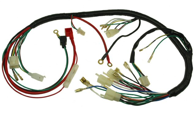
From wire harness design and component selection to prototyping, manufacturing, crimping, connector assembly, inspection, and testing, every stage can influence the reliability of the final product.
For electronic products that combine PCBs, PCB assemblies, connectors, cables, and wiring systems, Kingda provides PCB prototype manufacturing, quick-turn PCB prototyping, and PCB assembly solutions to support customers from initial design validation through production.
By applying a structured engineering approach and selecting every component according to its actual operating conditions, manufacturers can build custom wiring harnesses that deliver reliable electrical connectivity, mechanical durability, and consistent performance throughout the product lifecycle.