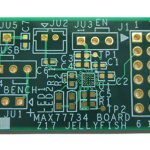
Zero Drift and Weighing Test on a Scale Main Board
A scale main board that reads correctly when it leaves the line can drift in the field for reasons that have nothing to do with the conversion chip. A slowly wandering zero or a display that keeps jumping may come from the load cell and its mounting, from the cable and its contacts, from a supply rail that is not stable, from the parameters of the analog front end, from residue left on the board, or from the filtering in the program. Replacing the ADC is rarely the first useful step, because it removes the part whose behaviour was most likely to have been correct.
Establish the Acceptance Condition and the Fixture
The weighing test becomes meaningful only when the conditions around it are fixed. The hardware revision, the program revision, the load cell model, the supply, the sampling period, the range of the test weights and the permitted error all belong in the record. The same load cell, cable, supply and program are then used with a known good board and with the board under investigation, so that the two results differ only by the board.
If the drift follows the load cell or the cable when they are exchanged, the board is not the variable to work on. If the drift stays with one board across every combination, the board level circuit becomes the subject. That single comparison removes a large part of the guesswork before any instrument is connected.
The fixture matters as much as the electronics. A platform that is not level, a bracket that has not settled, or a bench that transmits vibration produces a wandering reading with no electronic cause at all. Data recorded while the operator is resting a hand on the platform is not comparable with data recorded afterwards, so the loading and unloading sequence, and the wait between them, are kept identical.

Record the Analog Devices in Full
Project intake for this kind of product needs the Gerber data, the bill of materials, the placement coordinates, the assembly drawing, the program, the test requirement, the quantity and the lead time. Beyond that, the analog front end needs the instrument amplifier, the reference and the converter specified with full part numbers and parameters rather than by package.
Devices in an analog chain often share an outline while differing in offset, drift, noise and temperature behaviour. A substitution approved on the basis of the package alone changes the part of the circuit that sets the resolution of the whole instrument. Where a product exists in several capacity versions, each version needs its own bill of materials and its own program identified on the drawing, because a board built to one version and programmed for another can pass a rough functional check and still fail the acceptance test.
Our component procurement is where the approved part number and its documentation are held, and where substitutions are constrained to parts that have been reviewed rather than parts that happen to fit.
Work From the Supply and the Interface Outwards
Zero drift is investigated in an order. The load cell supply, the analog supply and the reference come first, because a shared rail that moves affects every channel at once, while a fault in one channel points at that channel alone. The sensor interface and the cable come next, followed by the input stage of the amplifier.
A loose terminal, a connector that has been disturbed or a screen that is no longer connected all change the reading. If the anomaly disappears when the cable is replaced, the original cable and its terminations are still examined, because a board that is only stable with one particular cable has not been repaired.
Shorting the input at the connector is a useful intermediate test. It separates the board from everything in front of it without disturbing the board itself, and the result says whether the remaining drift is generated on the board.
Residue and Its Limits as an Explanation
Where the input impedance at the front end is high, flux residue and other contamination on the board can influence what is measured. That is a real mechanism, but seeing residue is not the same as identifying it as the cause. The affected area and the network it touches are established first, and the cleaning method is then chosen from the solder material, the components and the customer requirement.
Automated optical inspection after SMT assembly covers missing parts, offset, bridging and the joints it can see, and it is the right tool for confirming that the assembly itself is sound. For a location that cannot be seen, the choice of a further method follows the failed reference designator and the customer requirement rather than a general rule.
When several boards from one batch show the same behaviour, the investigation widens to the material lot, the paste printing, the placement program and the reflow record, so that the point in the process where the deviation started can be identified. A batch wide symptom usually has a batch wide cause.
Closing a Repair Properly
If a specific joint or device is confirmed as the cause, the original data are saved before the repair and the same sensor, program, weights and timing are used afterwards. Seeing the zero return is not proof that the problem is solved. The settling time, the repeatability of loading and unloading, and the error against the permitted range are what show whether the instrument is back inside its specification.
If the data do not change after the repair, the investigation returns to the load cell, the cable, the supply and the program instead of continuing to exchange analog parts, because repeated substitution on the same position is a sign that the cause is elsewhere.
Making Batch Testing Comparable
Batch comparability comes from fixing the fixture, the load cell, the cable, the loading order and the waiting time. Boards of different capacity versions or program versions are tested separately so that their parameters are not mixed. The program revision is recorded at the time of programming and the test data are kept matched to the board serial number or to the batch.
Whenever a material is changed or the program is adjusted, the point at which the change begins is recorded. Without that, a shift in the data has no traceable origin, and a decision to rework a batch may be taken on the basis of two sets of numbers that were never comparable.
Our <a href="https://www.gopcba.com/pcba-testing/” title=”PCBA testing”>PCBA testing covers the assembly, the fitting of the analog devices, the programming and the weighing test, with the results retained against the build, and the whole flow sits inside our quality management system.
FAQ
Does a jumping display always mean a failed converter? No. The supply, the load cell, the cable and the fixture are all capable of producing the same symptom, and the comparison between a good board and a suspect board usually identifies which one it is.
Is residue enough to explain drift? It can influence a high impedance input, but the affected network is confirmed before cleaning is presented as the cure.
What ends the investigation? A repeat of the original loading sequence, with the same conditions, showing that the error and the settling time are back inside the accepted range.