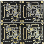
How to Manufacture High-Reliability 5G Base Station PCBs
A 5G base station board may sit in a cabinet for a decade, cycling through heat, cold and humidity. Its failure mode is rarely dramatic. A drifting dielectric, a voided lamination layer or a thin solder mask coating can degrade signal quality long before the unit stops working. Manufacturing reliability therefore starts with the material stack and the process window, not with the final inspection. This review walks through the decisions that matter on the line, from substrate choice to traceability records.
Each stage below feeds the next one. A substrate that absorbs moisture changes the lamination cycle. A lamination cycle that runs hot stresses the copper adhesion. Etching that drifts shifts impedance on every high-frequency trace. Buyers who understand this chain ask better questions during a supplier audit, and engineers who understand it write better process sheets. The goal is a board that behaves the same way in year eight as it did in the first article.
Material Choices That Set Reliability
The substrate sets the ceiling on everything that follows. A base station board needs a dielectric constant that stays stable across temperature and humidity swings. When that value drifts, impedance moves with it and high-frequency transmission loses accuracy. A low dissipation factor matters for the same reason, because it limits energy lost along the trace. Mechanical strength and aging resistance complete the picture, since the laminate must resist cracking and delamination over long outdoor exposure.
Copper foil carries the signal and holds the laminate together. High-purity copper supports efficient transmission, while strong adhesion keeps traces from peeling during thermal cycling and vibration. Corrosion resistance deserves the same attention, because humidity and airborne salts attack exposed copper edges. Solder mask adds a third layer of protection against moisture, dust and corrosive residue. For outdoor units, its chemical resistance, UV stability and high-temperature behavior decide how long that protection lasts.
Solder mask electrical properties also matter at high frequency. Its dielectric behavior and loss characteristics can shift signal response when traces run close to the surface. Specify a mask that suits the circuit, not just the color. Our quality management process ties incoming material verification to the approved material list, so a substitution never reaches the line without review. That discipline prevents a quiet material change from becoming a field failure.
Stackup and Lamination Control
Lamination bonds multiple layers into one structure, and multilayer 5G boards depend on it. Temperature, pressure and dwell time must stay inside a narrow window to achieve full bonding between layers. A cycle that runs cool or short leaves voids and bubbles. Those defects may pass initial inspection and then grow under repeated humidity and temperature cycling. Once delamination starts, structural integrity and impedance both suffer.
Thickness uniformity belongs in the same conversation. Uneven thickness across a panel shifts impedance and adds mechanical stress during assembly and thermal cycling. The press cycle, the prepreg flow and the tooling all influence that uniformity. Engineers should confirm the lamination profile against the laminate supplier data and then verify it with a coupon or cross-section. Documenting the profile for every lot makes repeat orders predictable rather than lucky.
Moisture in the prepreg is a quiet source of trouble. Laminate stored in humid air absorbs water, and that water turns to steam during the press cycle. The result is a scatter of small voids that a cross-section may miss at one point but that weaken the whole panel. A controlled drying step before layup, plus a check on shelf life and storage conditions, removes that risk before the press closes. Buyers should ask how prepreg is stored and how long it waits between thaw and use.
Etching and Surface Finish
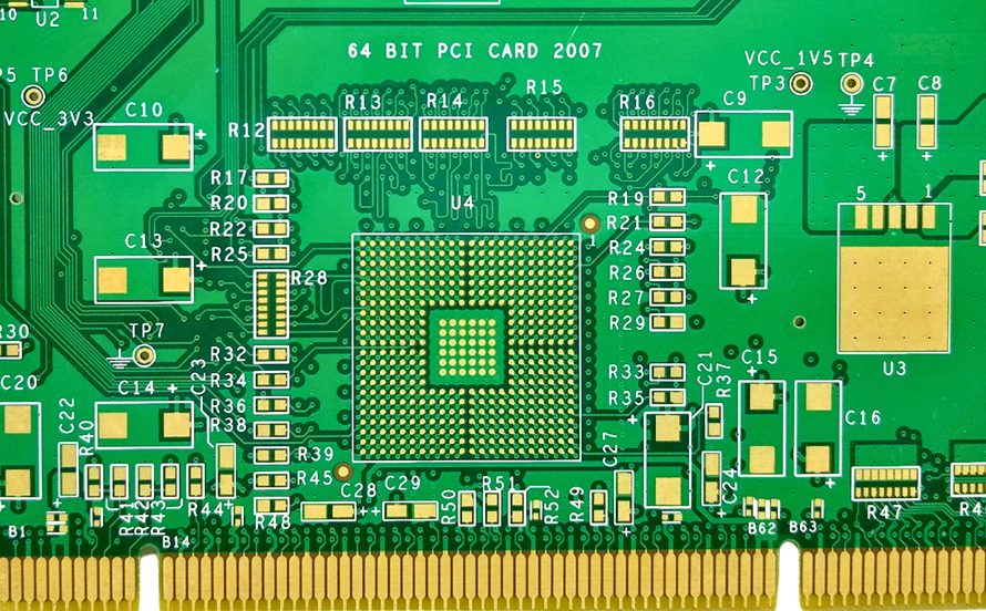
Etching defines the final trace geometry. Dense high-frequency routing leaves little margin, so etchant concentration, temperature and line speed all need control. Over-etching narrows traces and raises impedance. Under-etching leaves residual copper and creates shorts or stub effects. Burrs and rough trace edges add loss at high frequency. Checking trace width and edge quality after etch catches drift before panels move to the next step.
Surface finish protects exposed copper and prepares pads for soldering. ENIG and immersion silver are common choices for demanding boards, and each brings its own process controls. The coating must cover completely, because gaps expose copper to oxidation and corrosion. It must also stay uniform, since thick or uneven deposits can affect solderability and fine-pitch assembly. Buyers should confirm the finish, the thickness target and the inspection method before release.
Each finish carries a specific failure mode worth naming. Immersion silver can tarnish when packaging or storage lets sulfur reach the surface, which raises contact resistance and hurts solder wetting. ENIG can suffer nickel corrosion when the bath chemistry drifts, and that shows up later as brittle joints. Neither problem appears in a visual check alone. Buyers should ask for bath analysis records and a stated shelf life, then confirm the packaging keeps moisture and sulfur away from the panels.
When a design moves from engineering samples into a pilot build, the process plan should carry over unchanged. Our rapid PCBA prototyping service helps teams validate the stackup and finish on real boards before committing to volume. Early samples reveal pad geometry problems and process sensitivity while changes are still inexpensive.
Drilling and Dimensional Risk
Drill accuracy affects layer registration, via reliability and impedance on controlled traces. Small positional errors can break the connection between inner layers or leave an annular ring too thin for long-term thermal cycling. Drill wear, spindle runout and entry material all contribute to variation. A defined drill bit change schedule and routine hole inspection keep that variation inside the window as the lot progresses.
Registration between layers deserves the same scrutiny. Each lamination cycle can shift the panel slightly, and small shifts accumulate across a thick stackup. Checking registration coupons after each press cycle shows whether the process is drifting. Catching that drift early avoids scrapping finished boards that only fail at electrical test. Dimensional checks on panel size and warp also protect downstream assembly, since a warped board can misplace components during placement.
Via quality is where drilling and plating meet. A rough barrel wall or a thin plated layer may pass a quick check and then crack after a few hundred thermal cycles. Thermal stress testing on a coupon exposes that weakness before the design reaches the field. Buyers should ask how plated thickness is measured, whether it is checked on a coupon or on production holes, and what happens when a reading falls below the agreed limit.
Inspection and Test Coverage
Testing verifies what the process claims. Incoming material checks cover dielectric performance, copper adhesion, corrosion resistance and solder mask durability. After lamination, non-destructive inspection looks for voids and delamination. After etching, trace geometry and edge quality get measured. After surface finish, coating thickness and coverage are confirmed. Each check closes a loop back to a process parameter, so a defect points to a cause rather than a mystery.
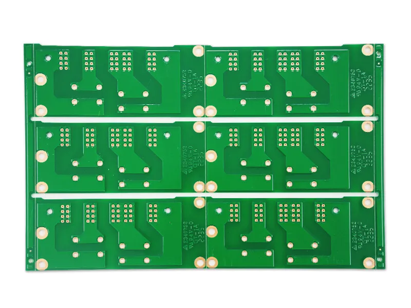
Finished boards need electrical and environmental verification as well. Temperature and humidity cycling, vibration and extended operation reveal weaknesses that a static test cannot. Electrical performance, structural integrity and conductivity should be monitored throughout the test. When a result falls outside the expected range, review the material and process records before the product enters regular production. Our PCBA testing team builds the test plan around the actual use case rather than a generic template.
Production Management and Traceability
Consistent quality across batches depends on people, equipment and records. Operators should understand why a parameter window exists before they adjust it. Inspectors should recognize real defects rather than pass panels by habit. Equipment such as lamination presses, etchers, drills and surface treatment lines needs scheduled calibration and preventive maintenance. A press that loses pressure control quietly changes every board that passes through it that shift.
Traceability ties the whole system together. Records should capture material batches, equipment used, process parameters, inspection results and production dates. If a problem appears after deployment, those records narrow the investigation quickly. They also support batch-to-batch comparison, so a slow drift becomes visible before it becomes scrap. For repeat orders, the same records let a factory reproduce a proven process instead of rebuilding it from memory.
Assembly planning belongs in the same review when the board also carries components. Our PCB assembly team coordinates fabrication, sourcing and build under one process sheet, which keeps the lamination and assembly windows aligned. For designs that combine both stages, SMT PCB assembly planning should start while the bare board is still in fabrication.
What Buyers Should Verify
Ask for the material list with the approved laminate and finish, and confirm that substitutions require written approval. Request the lamination profile and the coupon results that prove it. Ask how trace width and coating thickness are measured, and how often. Request the inspection plan for each critical stage, not just the final test report. These documents show whether a process is controlled in practice or only described in a brochure.
Confirm how the supplier handles a deviation. A factory that flags a drifting parameter before shipment is worth more than one that ships and hopes. Ask for the traceability record format and check that it is filled in for a real lot. Finally, agree on the acceptance criteria in writing before the first panel is pressed. Clear limits at the start cost little and prevent arguments later, when rework or a field return would cost far more than the review that avoided it.