Aerospace PCB Material Selection Guide: Key Materials and Requirements
Aerospace electronics operate in environments where temperature changes, vibration, mechanical shock, humidity, pressure variation, electromagnetic interference, and long service life can all affect PCB reliability. For this reason, selecting the right substrate and laminate is not simply a material purchasing decision. It is an engineering decision that directly influences electrical performance, mechanical stability, thermal behavior, manufacturability, and long-term reliability.
For an Aerospace PCB, material selection should begin with the actual operating environment and electrical requirements of the system. Aircraft avionics, radar, satellite communications, navigation equipment, UAVs, spacecraft, and other aerospace platforms may require very different material combinations.
A reliable selection process therefore needs to consider dielectric properties, thermal expansion, temperature resistance, mechanical strength, moisture resistance, weight, layer structure, signal frequency, manufacturing capability, material availability, and project-specific qualification requirements.
Key Requirements for Aerospace PCB Materials
The operating conditions of aerospace electronics can vary significantly. A PCB used inside an aircraft avionics module may experience repeated thermal cycling and vibration, while a satellite PCB may need to operate for many years without physical maintenance or replacement.
These different environments create several fundamental requirements for PCB materials.
Thermal Stability
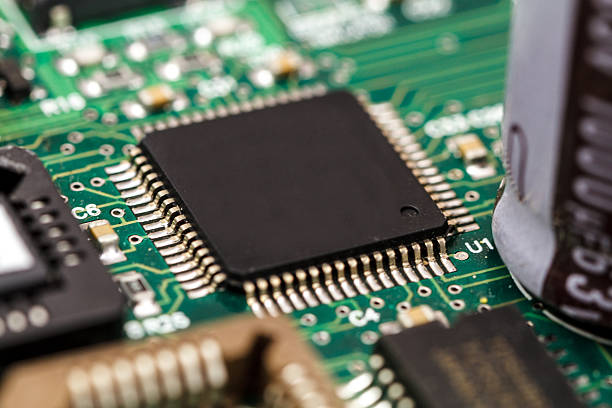
Temperature stability is one of the most important considerations when selecting aerospace PCB materials.
Electronic equipment may experience substantial temperature changes during operation, transportation, storage, launch, or flight. The selected laminate should maintain stable electrical and mechanical properties across the expected operating temperature range.
Important parameters include:
- Glass transition temperature (Tg)
- Decomposition temperature (Td)
- Coefficient of thermal expansion (CTE)
- Thermal conductivity
- Thermal cycling resistance
- Dimensional stability
CTE is particularly important for multilayer constructions because excessive mismatch between the PCB material and copper can increase mechanical stress during temperature cycling.
For demanding applications, engineers may consider high-Tg materials, polyimide systems, or other specialized laminates depending on the actual temperature profile and qualification requirements.
Electrical Performance and Signal Integrity
Electrical characteristics become increasingly important as aerospace electronics move toward higher data rates, RF systems, radar, satellite communications, and advanced navigation systems.
The dielectric constant (Dk) and dissipation factor (Df) of the laminate influence transmission-line behavior and signal loss. Material properties should therefore remain predictable across the intended operating frequency and temperature range.
For RF and microwave applications, low-loss materials can help reduce attenuation and support more predictable signal transmission.
GOPCBA provides advanced High-Frequency PCB manufacturing capabilities for applications requiring specialized laminates, multilayer structures, controlled impedance, and stable high-frequency electrical performance.
Material selection should also consider:
- Dielectric constant stability
- Dissipation factor
- Insulation resistance
- Breakdown strength
- Moisture absorption
- Frequency-dependent electrical characteristics
- Copper surface roughness
For high-speed and RF designs, material selection should be coordinated with stack-up development and impedance calculations rather than treated as a separate manufacturing decision.
Mechanical Strength and Structural Stability
Aerospace PCBs may be exposed to vibration, shock, acceleration, transportation stress, and mechanical constraints during their service life.
The laminate therefore needs sufficient mechanical strength and dimensional stability for the application.
Important characteristics include:
- Flexural strength
- Tensile strength
- Dimensional stability
- Z-axis expansion
- Peel strength
- Resistance to vibration and shock
For multilayer boards, Z-axis CTE is especially important because excessive expansion can place stress on plated through-holes and interlayer connections during repeated thermal cycling.
Mechanical requirements should be evaluated together with board thickness, copper weight, layer count, via structure, mounting method, and enclosure design.
Environmental Resistance
Aerospace electronics can encounter humidity, condensation, contaminants, temperature cycling, vibration, pressure changes, and other environmental stresses.
Material selection should therefore reflect the actual mission profile rather than relying on a generic “aerospace-grade” label.
Moisture absorption is particularly important because absorbed moisture can affect dielectric behavior, dimensional stability, insulation performance, and manufacturing processes.
For high-reliability applications, engineers should evaluate:
- Moisture absorption
- Thermal cycling
- Chemical resistance
- Surface insulation characteristics
- Dimensional stability
- Environmental aging
- Resistance to mechanical stress
The applicable environmental and qualification tests should be established according to the aircraft, spacecraft, subsystem, and customer requirements.
Lightweight and Compact PCB Structures
Aerospace systems place continuous pressure on designers to reduce weight and package volume while maintaining electrical and mechanical performance.
The PCB itself is only one part of the overall weight budget, but material selection can still contribute to system-level optimization.
Thin laminates, high-density interconnection technologies, rigid-flex constructions, and optimized multilayer stack-ups can help engineers integrate more functionality into a smaller footprint.
For designs requiring high routing density, Multilayer PCB technology can provide additional signal, power, and ground layers without requiring a proportionally larger board area.
However, reducing thickness or increasing density should not compromise mechanical strength, thermal performance, manufacturability, or reliability.
Key Factors When Selecting Aerospace PCB Materials
Selecting a suitable material requires more than comparing datasheet values. The material must be compatible with the complete PCB structure and the intended manufacturing process.
Electrical Requirements
Start by identifying the operating frequency, signal speed, impedance targets, power requirements, and expected electrical environment.
For RF and high-speed circuits, Dk, Df, copper roughness, dielectric thickness, and stack-up geometry all influence signal integrity.
A controlled-impedance design should therefore be developed together with the material selection process.
GOPCBA’s PCB Manufacturing capabilities cover multilayer, high-frequency, high-speed, HDI, rigid-flex, heavy-copper, and controlled-impedance PCB technologies for demanding electronic applications.
Thermal Requirements
The expected operating and storage temperature ranges should be defined before selecting the laminate.
Engineers should evaluate Tg, Td, CTE, thermal conductivity, and thermal cycling behavior according to the application.
High-temperature environments may require specialized materials, but the highest-temperature material is not automatically the best choice. Material selection should balance thermal performance with electrical characteristics, mechanical properties, manufacturability, availability, and cost.
Mechanical Requirements
Mechanical loading should be evaluated at the system level.
For example, a PCB mounted close to a vibrating engine or other mechanical source may require different structural considerations from a board installed in a relatively protected avionics enclosure.
Board thickness, copper distribution, via structure, mounting points, stiffeners, and laminate properties should all be considered together.
Manufacturing Compatibility
A material may have excellent electrical or thermal properties but still create manufacturing challenges.
Specialized laminates can have different drilling, lamination, desmear, plating, and dimensional-control requirements compared with conventional FR-4 materials.
The manufacturer should therefore evaluate the selected material before production to confirm that the required layer structure, via technology, registration accuracy, surface finish, and inspection methods can be achieved consistently.
Common Aerospace PCB Material Types
Several material families are commonly considered for aerospace and high-reliability electronics. The appropriate choice depends on the application rather than a universal ranking.
Polyimide Materials
Polyimide is widely associated with demanding electronic applications because of its thermal stability, flexibility, and useful mechanical and electrical characteristics.
It can be considered for applications involving thermal cycling, flexible circuits, rigid-flex structures, and other environments where dimensional and thermal performance are important.
Polyimide is particularly relevant when packaging flexibility or repeated mechanical movement is part of the design.
However, the specific polyimide system, construction, and qualification requirements should always be evaluated against the application.
Modified PPO/PPE Materials
Polyphenylene oxide/polyphenylene ether-based systems can provide favorable dielectric properties and low-loss characteristics for high-frequency applications.
These materials may be considered for RF, communication, radar, and other circuits where electrical performance is a major design priority.
Material selection should consider the complete laminate system, including resin formulation, reinforcement, copper foil, dielectric thickness, and manufacturing process.
High-Performance Epoxy Systems
Modified epoxy laminates can provide a practical balance between electrical performance, mechanical strength, thermal properties, manufacturability, and cost.
High-Tg FR-4 and other enhanced epoxy systems may be suitable for aerospace electronics where extreme RF performance is not the primary requirement.
The appropriate grade should be selected according to the actual thermal, mechanical, electrical, and qualification requirements.
For mission-critical designs, standard commercial FR-4 should not automatically be treated as equivalent to a qualified high-reliability material system.
High-Frequency Materials for Aerospace RF Applications
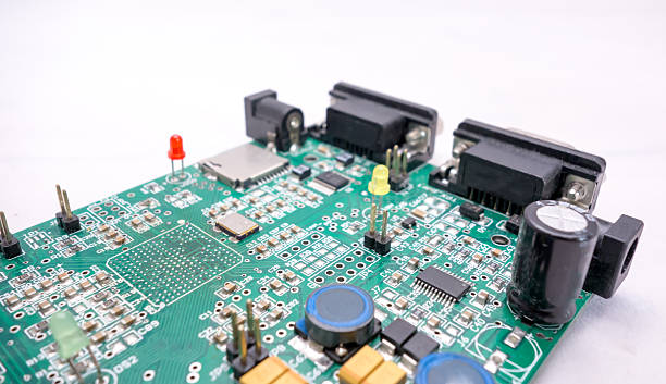
Radar, satellite communication, navigation, telemetry, and other RF systems often require tighter control of signal integrity.
For these applications, low-loss materials such as PTFE-based systems, Rogers materials, and other specialized RF laminates may be considered depending on the frequency range and electrical requirements.
Material selection should take into account:
- Dk and Df
- Frequency stability
- Thermal stability
- Copper roughness
- Moisture absorption
- Dimensional stability
- Processing requirements
- Availability and supply continuity
The material should then be integrated into the PCB stack-up and impedance design.
GOPCBA’s high-frequency manufacturing solutions support specialized RF materials, controlled-impedance construction, multilayer structures, HDI, and other advanced PCB technologies.
Material Selection for Multilayer Aerospace PCBs
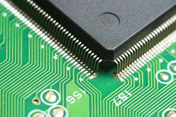
Aerospace electronics frequently require multilayer architectures to separate signal, power, and ground structures while maintaining compact dimensions.
For a multilayer board, material selection must consider the complete stack-up rather than individual laminates in isolation.
Engineers need to evaluate:
- Number of layers
- Copper thickness
- Dielectric thickness
- Resin content
- Dk and Df
- CTE
- Layer registration
- Via structure
- Impedance requirements
- Thermal distribution
For high-speed or RF designs, the distance between signal layers and reference planes can directly affect impedance. This makes material thickness and dielectric characteristics critical design parameters.
GOPCBA’s engineering approach combines stack-up review, material selection, impedance analysis, DFM evaluation, and manufacturing verification for complex multilayer and high-frequency PCB projects.
Compliance, Qualification, and Traceability
Aerospace PCB material selection should also address quality documentation and supply-chain control.
The exact standards depend on the application, customer, product category, and program requirements. Depending on the project, requirements may involve applicable IPC standards, aerospace quality systems, customer specifications, environmental testing, material certifications, and other qualification procedures.
Material traceability is particularly important for high-reliability electronics.
Manufacturers may need to maintain records covering:
- Material manufacturer
- Material grade
- Lot or batch number
- Certificates of conformity
- Incoming inspection
- Storage conditions
- Production records
- Inspection results
- Test data
- Engineering changes
This information can become essential when supporting long product lifecycles, qualification activities, failure analysis, or future production.
How to Choose the Right Aerospace PCB Manufacturer
Material selection and PCB manufacturing should not be separated.
A technically capable manufacturer should be able to review the material, stack-up, fabrication requirements, and testing strategy before production begins.
When evaluating a supplier, consider the following capabilities:
Engineering Support
The manufacturer should be able to support:
- DFM analysis
- Stack-up development
- Material evaluation
- Controlled impedance
- High-speed and RF design review
- Thermal considerations
- Via and drilling technology
- Prototype development
Manufacturing Capabilities
Depending on the project, useful capabilities may include:
- Multilayer PCB fabrication
- HDI and microvia technology
- High-frequency PCB manufacturing
- Rigid-flex PCB manufacturing
- Controlled-impedance fabrication
- Precision drilling
- Advanced lamination
- AOI inspection
- Electrical testing
- Cross-section analysis
Quality and Documentation
High-reliability projects require disciplined process control.
A supplier should have appropriate procedures for material control, process inspection, final inspection, testing, documentation, and traceability.
For aerospace and satellite applications, the manufacturing approach should be matched to the actual qualification and customer requirements rather than relying solely on generic industry claims.
Conclusion
Selecting materials for an Aerospace PCB is a multidisciplinary engineering process involving electrical performance, thermal stability, mechanical strength, environmental resistance, manufacturing compatibility, reliability, and supply-chain considerations.
Polyimide, modified PPO/PPE, high-Tg epoxy, PTFE-based materials, Rogers laminates, and other specialized systems can each serve different requirements. There is no single material that is optimal for every aerospace application.
The best approach is to begin with the actual mission profile, define the electrical and mechanical requirements, develop the stack-up, evaluate thermal and environmental conditions, confirm manufacturing compatibility, and establish the necessary qualification and traceability requirements.
As aerospace systems continue to evolve toward advanced avionics, satellite communications, radar, autonomous platforms, high-speed data processing, and increasingly compact electronic architectures, the demand for reliable materials and precision High-Reliability PCB manufacturing will continue to increase.
For demanding aerospace projects, GOPCBA can support material selection, multilayer fabrication, high-frequency PCB manufacturing, controlled-impedance construction, HDI, PCB assembly, inspection, and production engineering within an integrated manufacturing workflow.