FR4 PCB High-Frequency PCB Materials: Key Differences and Applications
Choosing the right substrate is one of the most important decisions in PCB development. Material properties directly affect impedance, signal integrity, thermal performance, mechanical reliability, manufacturing cost, and long-term product performance.
Among the many PCB substrate options available today, FR4 and high-frequency laminates are two of the most commonly considered materials. FR4 provides a strong balance of performance, manufacturability, availability, and cost, while high-frequency materials are designed to provide more stable electrical characteristics for demanding RF and high-speed applications.
The right choice is not simply a matter of deciding which material is “better.” Instead, engineers need to match the PCB material to operating frequency, signal speed, dielectric requirements, thermal conditions, mechanical constraints, and project budget.
1. What Is FR4?
FR4 is a widely used PCB substrate based primarily on woven glass fiber reinforcement and epoxy resin.
It has become the standard material for a large range of electronic products because it offers a well-balanced combination of:
- Mechanical strength
- Electrical insulation
- Thermal performance
- Moisture resistance
- Manufacturing compatibility
- Cost efficiency
A properly designed FR4 PCB can meet the requirements of many digital, analog, industrial, consumer, automotive, and control applications.
However, FR4 is not a single material with one fixed dielectric constant or loss characteristic. Different FR4 systems can have significantly different electrical properties, especially as frequency increases. Therefore, engineers should use the actual material datasheet rather than relying on a generic FR4 value when precise impedance or high-speed performance is required.
2. What Are High-Frequency PCB Materials?
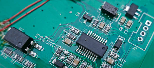
High-frequency PCB materials are engineered for applications where signal loss, dielectric stability, impedance consistency, and high-speed electrical performance are especially important.
Depending on the application, these materials may use PTFE-based systems, modified epoxy systems, hydrocarbon/ceramic materials, or other specialized resin technologies.
Compared with conventional FR4, many high-frequency laminates offer:
- Lower dielectric loss
- More controlled dielectric properties
- Better high-frequency signal performance
- More predictable impedance behavior
- Improved performance at RF and microwave frequencies
These characteristics make a high-frequency PCB suitable for demanding applications such as RF communication, radar, wireless infrastructure, satellite electronics, and high-speed data transmission.
However, high-frequency laminates can be more expensive and may require specialized manufacturing processes.
3. Key Difference: Dielectric Performance
One of the most important differences between FR4 and high-frequency materials is their dielectric behavior.
FR4 Dielectric Characteristics
FR4 provides suitable dielectric performance for a broad range of conventional applications. At lower and moderate frequencies, its electrical properties can be adequate for many designs.
As frequency increases, however, engineers need to consider factors such as:
- Frequency-dependent dielectric constant
- Dissipation factor
- Resin content
- Glass weave effects
- Material construction
- Actual transmission-line geometry
These factors can influence signal propagation and impedance.
For basic applications, these effects may have little practical impact. For high-speed interfaces or RF circuits, they can become important design considerations.
High-Frequency Materials
High-frequency laminates are generally optimized for more stable and lower-loss electrical performance.
Lower dielectric loss can reduce signal attenuation, while controlled dielectric characteristics can make impedance calculations and transmission-line design more predictable.
This is particularly valuable when the design contains long high-speed traces, RF transmission lines, tightly controlled impedance, or microwave circuits.
4. Signal Integrity and Impedance Control
For an impedance control PCB, material selection is directly connected to signal integrity.
The characteristic impedance of a transmission line depends on several variables, including:
- Trace width
- Copper thickness
- Dielectric thickness
- Dielectric constant
- Transmission-line structure
- Reference-plane configuration
- Manufacturing tolerances
With FR4, impedance control is achievable when the material properties and stackup are properly characterized and manufacturing tolerances are tightly controlled.
For high-frequency applications, however, material selection becomes increasingly important because dielectric properties can vary with frequency.
High-frequency laminates can provide a more controlled electrical environment, helping engineers maintain the required impedance and reduce transmission loss.
For complex designs, material selection should therefore be coordinated with the PCB stackup and routing strategy during the engineering stage. Our PCB Design & Layout service can help integrate these considerations into the board design process.
5. Signal Loss: When Does It Matter?
Signal loss becomes increasingly important as frequency and data rates increase.
The total transmission loss of a PCB interconnect can be influenced by both conductor loss and dielectric loss.
FR4
FR4 can perform very well for many conventional digital and analog circuits. However, its loss characteristics may become less favorable as signal frequency increases.
For shorter interconnects or moderate-speed applications, this may not be a significant limitation.
For long transmission paths, high data rates, or RF signals, however, designers may need to evaluate insertion loss more carefully.
High-Frequency Materials
Specialized high-frequency materials are generally selected when minimizing transmission loss is a major design objective.
They can be especially useful when the system requires:
- Low-loss RF transmission
- High-frequency signal integrity
- Long transmission paths
- High-speed serial interfaces
- Stable microwave performance
- Controlled impedance over demanding frequency ranges
Material selection should always be based on the actual frequency range and electrical requirements rather than simply choosing a material labeled “high frequency.”
6. Thermal and Mechanical Performance
Electrical characteristics are not the only factors that matter.
A PCB substrate must also withstand the thermal and mechanical conditions associated with assembly and operation.
FR4
FR4 offers good mechanical strength and has a long-established manufacturing ecosystem.
Its characteristics make it suitable for many applications involving:
- Standard SMT assembly
- Through-hole components
- Multilayer PCB fabrication
- Industrial control
- Consumer electronics
- General-purpose computing hardware
Its mature processing characteristics also make production relatively straightforward.
High-Frequency Materials
High-frequency materials vary considerably from one formulation to another.
Some specialized materials can have different mechanical properties, coefficient of thermal expansion, dimensional stability, or processing requirements compared with conventional FR4.
This means material selection should consider not only electrical specifications but also:
- Lamination compatibility
- Drilling requirements
- Copper adhesion
- Thermal expansion
- Moisture behavior
- Surface finish compatibility
- Assembly temperature
- Long-term reliability
For hybrid designs combining FR4 and high-frequency materials, manufacturing process control becomes especially important.
7. Manufacturing Cost and Availability
Cost is another major difference.
FR4 is manufactured at very large scale and is available in a wide variety of grades and thicknesses. Its mature supply chain helps keep material and manufacturing costs relatively competitive.
High-frequency materials generally cost more because of their specialized resin systems, reinforcement structures, manufacturing requirements, and performance characteristics.
Therefore, using a high-frequency laminate when the application does not actually require it can unnecessarily increase the project cost.
Conversely, selecting a low-cost material for a circuit that requires tightly controlled RF or high-speed performance can create signal-integrity problems later in development.
A professional PCB material selection process should therefore balance electrical performance against manufacturing cost rather than focusing on either factor independently.
For projects ranging from prototypes to production quantities, PCB Manufacturing can be coordinated with the selected material system and required fabrication specifications.
8. FR4 vs. High-Frequency Materials: Application Comparison
FR4 Is Often Suitable For:
- Consumer electronics
- Industrial control boards
- General-purpose computer hardware
- Power-control electronics
- Sensors
- Conventional embedded systems
- Standard digital circuits
- Low- to moderate-frequency analog circuits
FR4 is particularly attractive when the design requires reliable performance without the additional cost of specialized high-frequency laminates.
High-Frequency Materials Are Often Suitable For:
- RF communication equipment
- Radar systems
- Wireless infrastructure
- Microwave electronics
- Satellite communication
- High-speed networking
- RF test equipment
- High-frequency signal-processing systems
These applications place greater emphasis on dielectric loss, impedance stability, propagation characteristics, and overall signal integrity.
9. Can FR4 and High-Frequency Materials Be Used Together?
Yes. Hybrid PCB construction can combine different laminate systems within the same board when the design requires both conventional and high-frequency performance.
For example, a PCB may use FR4 for sections containing standard digital circuitry while using a specialized high-frequency material for RF transmission paths.
This approach can provide a balance between electrical performance and cost.
However, hybrid construction introduces additional manufacturing considerations, including:
- Material compatibility
- Lamination parameters
- Coefficient of thermal expansion
- Resin flow
- Layer registration
- Drilling
- Plating
- Thermal stress
- Final board flatness
The stackup should therefore be designed with the manufacturing process in mind from the beginning.
10. How to Select the Right PCB Material
Instead of choosing a material based solely on frequency, engineers should evaluate the entire application.
Step 1: Define the Operating Frequency
Determine the actual frequency range of the signals traveling through the PCB.
A conventional FR4 material may be sufficient for many lower-frequency applications, while RF and microwave circuits may require specialized laminates.
Step 2: Define the Signal Integrity Requirements
Consider:
- Maximum insertion loss
- Return loss
- Required impedance
- Crosstalk
- Rise time
- Data rate
- Trace length
These factors can help determine whether a conventional material is sufficient.
Step 3: Evaluate Thermal Requirements
Consider operating temperature, assembly temperature, thermal cycling, and heat dissipation requirements.
The electrical material specification should not be evaluated separately from thermal reliability.
Step 4: Consider Manufacturing Capability
The selected material must be compatible with the intended fabrication process.
Working with an experienced manufacturer early in the design process can help identify potential issues before production begins.
Step 5: Balance Performance and Cost
Do not automatically choose the most expensive material.
The objective is to select a material that provides sufficient electrical, thermal, mechanical, and reliability performance at an appropriate cost.
For early-stage products, Prototype PCB Assembly can be used to validate the complete design and assembly approach before moving into larger production volumes.
11. FR4 vs. High-Frequency PCB Materials Comparison
| Property | FR4 | High-Frequency Materials |
|---|---|---|
| General-purpose use | Excellent | Usually unnecessary |
| Cost | Lower | Higher |
| Manufacturing maturity | Excellent | Depends on material |
| Mechanical strength | Generally good | Material dependent |
| High-frequency loss | Moderate to material-dependent | Generally lower |
| Dielectric stability | Material/frequency dependent | Generally more controlled |
| Impedance control | Good with proper design | Excellent for demanding applications |
| RF applications | Limited to suitable designs | Highly suitable |
| High-speed applications | Suitable for many designs | Preferred for demanding designs |
| Material availability | Very broad | More specialized |
12. Conclusion
FR4 and high-frequency PCB materials are not direct substitutes in every application. Each has a specific role within PCB engineering.
FR4 remains an excellent choice for many conventional electronic products because of its balanced electrical performance, mechanical strength, manufacturing maturity, and cost efficiency.
High-frequency materials become more valuable when signal loss, dielectric stability, impedance accuracy, and RF performance become critical design requirements.
The most effective approach is to select the substrate based on actual electrical frequency, signal-integrity targets, thermal conditions, mechanical requirements, manufacturing capabilities, and budget.
For demanding applications, material selection should also be integrated with stackup design, impedance calculations, fabrication tolerances, and assembly requirements. A well-coordinated design-to-manufacturing process can help ensure that the selected material delivers the expected performance in the finished product.
For projects requiring both PCB fabrication and assembly, PCB Assembly provides a path from fabricated boards to assembled prototypes and production-ready electronic assemblies.