Motherboard PCB Layers: PCB Layer Count, Stackup & Multilayer PCB Design Guide
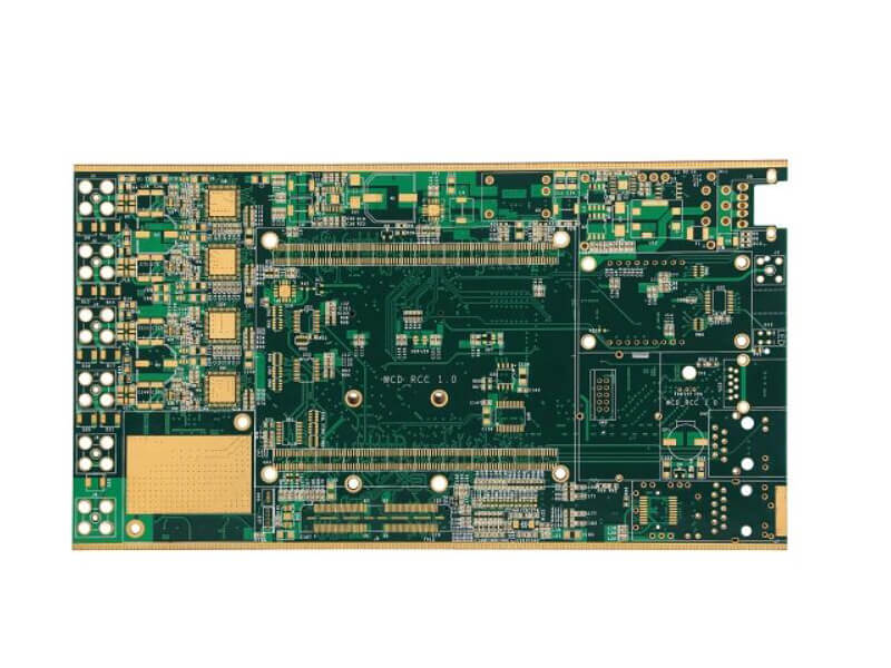
A motherboard is the central circuit platform of a computing, communication, or automation system. It connects processors, memory, storage devices, interfaces, power circuits, and peripheral components, enabling the system to receive inputs, process data, generate outputs, and communicate with other devices.
As modern electronic systems become more powerful while product dimensions continue to shrink, motherboard designs require increasingly dense interconnections. This makes the PCB layer count an important design consideration. Instead of placing all routing on the top and bottom surfaces, engineers use a carefully engineered multilayer structure to accommodate high-speed signals, power distribution, ground references, and complex component interconnections.
So, how many PCB layers does a motherboard have? There is no single universal answer. Depending on system complexity, signal speed, component density, power requirements, mechanical constraints, and manufacturing technology, a motherboard PCB may use 4, 6, 8, 10, 12, 16, 20, 24, or even more copper layers.
This guide explains typical motherboard PCB layers, why multilayer construction is necessary, and how engineers develop an effective PCB stackup for modern motherboard applications.
How Many PCB Layers Does a Motherboard Have?
When discussing PCB layer count, engineers generally refer to the number of conductive copper layers used for routing and power distribution. Solder mask, silkscreen, and other surface features are not normally counted as copper layers.
Each copper layer can be assigned a specific purpose, such as high-speed signal routing, low-speed signals, power distribution, or ground reference. Dielectric materials separate the conductive layers and determine important electrical characteristics such as impedance and signal propagation.
The appropriate layer count depends heavily on the motherboard’s application.
1. Entry-Level Motherboard PCB: 4 Layers
A 4-layer PCB can be sufficient for relatively simple electronic systems with moderate routing density and signal-speed requirements.
A typical four-layer structure may include:
- Top signal/component layer
- Internal ground or power plane
- Internal power or signal layer
- Bottom signal/component layer
However, the exact arrangement depends on the design requirements. Modern boards may use internal layers for both signal routing and power distribution rather than assigning one entire layer exclusively to power.
Four-layer construction provides a reasonable balance between cost and routing capability, but it can become restrictive when a motherboard contains high-speed interfaces, dense BGA packages, multiple power domains, or strict electromagnetic compatibility requirements.
2. Mid-Range Motherboard PCB: 6 to 8 Layers
Many moderately complex computing, industrial, communication, and embedded systems use 6-layer PCB or 8-layer PCB structures.
Additional copper layers provide more routing channels and allow designers to position signal layers next to appropriate reference planes. This is particularly important for high-speed interfaces because the distance between a signal trace and its reference plane strongly affects controlled impedance and electromagnetic behavior.
A typical eight-layer stackup may contain a combination of:
- High-speed signal layers
- General signal-routing layers
- Ground planes
- Power planes
- Additional routing layers for lower-speed interfaces
The exact stackup should be determined through electrical simulation, impedance calculations, power-distribution requirements, and manufacturing capabilities rather than following a fixed layer arrangement.
3. High-Performance Motherboard PCB: 10 to 16+ Layers
More complex systems may require 10-layer PCB, 12-layer PCB, 14-layer PCB, 16-layer PCB, or higher.
These boards are commonly associated with applications involving:
- High-performance processors
- Large BGA packages
- DDR memory
- PCIe and other high-speed interfaces
- Multiple power rails
- High-density I/O
- Advanced networking
- Industrial computing
- Server and embedded computing systems
As the PCB layer count increases, engineers gain greater freedom to separate routing functions, establish stable reference planes, and manage power distribution.
However, adding layers is not automatically a solution to every signal-integrity problem. Poor stackup planning, excessive via transitions, inappropriate reference-plane changes, and inadequate return-path design can still cause significant electrical problems.
4. High-Layer-Count and Specialized Motherboards
Some advanced computing, telecommunications, aerospace, defense, and other high-reliability systems can require more than 20 copper layers.
A 20-layer PCB or 24-layer PCB can provide extensive routing resources for highly integrated systems. In some specialized applications, even higher layer counts may be technically feasible.
At this level, PCB design becomes significantly more complicated. Engineers must carefully manage:
- Layer-to-layer registration
- Controlled impedance
- Power integrity
- Signal integrity
- Thermal distribution
- Via structures
- Material selection
- Lamination
- Warpage
- Manufacturing yield
- Testing and inspection
Therefore, the highest possible layer count is not necessarily the best design. The goal is to achieve the required electrical and mechanical performance with a practical and manufacturable stackup.
Why Do Motherboards Need Multilayer PCBs?
A motherboard may contain hundreds or thousands of electrical connections between processors, memory devices, connectors, controllers, power-management circuits, and other components.
Trying to route all of these connections on only two copper layers would create severe space, signal-integrity, and manufacturing problems. A multilayer PCB provides additional routing resources while allowing engineers to create dedicated reference structures for high-speed signals and power distribution.
Complex PCB Routing
Modern motherboard designs often contain high-density BGA packages, fine-pitch components, connectors, and numerous passive components.
BGA devices are particularly challenging because connections are distributed across an array of solder balls underneath the package. Routing these connections may require multiple signal layers and carefully designed via structures.
A multilayer structure allows designers to distribute routing across different copper layers instead of forcing all connections onto the outer surfaces.
This can help:
- Reduce routing congestion
- Shorten critical signal paths
- Reduce unnecessary trace crossings
- Improve component escape routing
- Support high-density interconnects
- Provide better return-current paths
For highly integrated boards, HDI technology may also be used. Microvias, blind vias, and sequential lamination can provide additional routing flexibility where conventional through-hole vias would consume too much board area.
Power, Ground, and Signal Reference Planes
Power distribution is another major reason why motherboards use multiple layers.
Modern processors, memory devices, chipsets, and peripheral ICs can operate with several different voltage domains. A motherboard may therefore require multiple power rails, ground connections, and carefully controlled current paths.
Dedicated or partially dedicated power and ground structures can reduce routing congestion and improve power-distribution performance.
Ground planes are especially important for high-speed signals because they provide a low-inductance return-current path and serve as reference planes for controlled-impedance routing.
However, not every internal layer needs to be a complete power or ground plane. Depending on the design, some layers may combine signal and power routing, while others may be dedicated reference planes.
The correct configuration depends on:
- Current requirements
- Voltage domains
- Signal speeds
- Layer spacing
- Component placement
- Power integrity targets
- Manufacturing constraints
Impedance Control and Signal Integrity
As data rates increase, signal integrity becomes one of the most important factors determining motherboard layer count.
High-speed interfaces such as PCIe, DDR memory, USB, Ethernet, and other serial or parallel interfaces require carefully controlled transmission-line characteristics.
The impedance of a PCB trace depends on several factors, including:
- Trace width
- Copper thickness
- Dielectric thickness
- Dielectric constant
- Distance to the reference plane
- Trace geometry
- Differential-pair spacing
This means the PCB stackup must be designed before final routing begins.
For example, placing a high-speed signal layer close to a continuous ground reference can provide a more predictable return path. Conversely, routing a high-speed trace across a split or discontinuous reference plane can increase return-path discontinuity and electromagnetic radiation.
A properly engineered stackup can therefore improve:
- Controlled impedance
- Signal quality
- Crosstalk performance
- Electromagnetic compatibility
- Differential-pair routing
- Timing consistency
Functional Layer Allocation
A motherboard PCB can be divided into different functional areas, including:
- CPU and chipset region
- Memory region
- Power-management region
- High-speed interface region
- Storage interface region
- I/O and connector region
- Low-speed control region
The PCB layer count determines how much routing freedom engineers have when connecting these functional areas.
For example, high-speed differential pairs may receive dedicated routing layers with controlled reference planes, while lower-speed control signals can use general-purpose routing layers.
This functional approach helps designers organize the board more effectively while reducing unnecessary routing conflicts.
PCB Size and Manufacturing Considerations
Increasing the number of PCB layers provides more electrical design flexibility, but it also increases manufacturing complexity and cost.
A multilayer PCB requires multiple lamination processes, accurate layer registration, drilling, copper plating, etching, inspection, and electrical testing. As layer count increases, manufacturing tolerances and material selection become increasingly important.
Engineers should therefore consider PCB manufacturability during the stackup-design stage.
Important considerations include:
- Finished board thickness
- Copper thickness
- Dielectric materials
- Layer registration
- Hole size and aspect ratio
- Via structure
- Impedance requirements
- Lamination process
- Board warpage
- Thermal expansion
- Surface finish
- Fabrication tolerances
A technically impressive design may still be unsuitable for mass production if its fabrication requirements exceed the manufacturer’s process capabilities.
Motherboard PCB Stackup Design
A PCB stackup defines how copper layers and dielectric materials are arranged throughout the board.
A typical multilayer motherboard contains a combination of signal, ground, and power layers. The top and bottom layers generally accommodate components, connectors, and accessible routing, while internal layers provide additional routing and reference structures.
A simplified example of an eight-layer arrangement could be:
| Layer | Typical Function |
|---|---|
| L1 | Components and high-speed signals |
| L2 | Ground reference |
| L3 | High-speed/general signal routing |
| L4 | Power distribution |
| L5 | Power/ground or signal routing |
| L6 | High-speed/general signal routing |
| L7 | Ground reference |
| L8 | Components and signal routing |
This is only an illustrative structure. The optimal stackup must be developed according to the actual impedance, power, thermal, material, and manufacturing requirements of the motherboard.
Controlled Impedance
For high-speed designs, engineers typically calculate the required trace geometry based on the selected dielectric thickness and material properties.
Common controlled-impedance structures include:
- Microstrip
- Stripline
- Embedded stripline
- Differential-pair transmission lines
The relationship between the signal layer and its reference plane is especially important. Therefore, changing dielectric thickness during stackup development can require corresponding changes to trace width and spacing.
Via Structures
Vias connect different copper layers and are essential to multilayer motherboard routing.
Common structures include:
- Through vias
- Blind vias
- Buried vias
- Microvias
- Stacked microvias
- Staggered microvias
Advanced HDI PCB construction can reduce the space consumed by conventional through-hole vias and provide greater routing density around fine-pitch BGA components.
However, advanced via structures also increase fabrication complexity and cost, so they should be used where the electrical and mechanical requirements justify them.
Symmetry and Mechanical Stability
A well-designed multilayer stackup should generally maintain a balanced and mechanically stable construction.
Symmetrical copper distribution and appropriately selected dielectric structures can help reduce:
- Board warpage
- Uneven thermal expansion
- Lamination stress
- Mechanical deformation
This does not mean that every PCB must use an identical number of layers above and below the centerline. Instead, the overall stackup should be engineered to maintain reasonable mechanical balance and predictable manufacturing behavior.
Similarly, odd-layer-count PCBs are not inherently unacceptable. A well-engineered odd-layer stackup can be manufactured successfully. The key consideration is whether the stackup is electrically, mechanically, and thermally balanced and can be manufactured reliably.
How to Choose the Right Motherboard PCB Layer Count
Determining the appropriate PCB layer count should be a systematic engineering decision rather than simply selecting a higher number of layers.
Consider the following factors:
1. Component Density
A motherboard with large BGA packages and dense I/O generally requires more routing resources than a simple controller board.
2. Signal Speed
Higher data rates usually require more careful reference-plane and impedance control. This may increase the need for additional signal and reference layers.
3. Power Distribution
Multiple voltage domains and high-current power delivery can require dedicated power-routing areas, planes, copper pours, or additional layers.
4. Board Size
A smaller motherboard may require more layers to accommodate the same number of electrical connections that could otherwise be distributed across a larger board.
5. Thermal Requirements
Layer count alone does not determine thermal performance. Copper thickness, copper area, thermal vias, component placement, heat spreaders, airflow, and the PCB material system all contribute to thermal management.
6. Manufacturing Capability
The selected PCB manufacturer must be capable of reliably producing the required layer count, board thickness, copper weight, via structures, tolerances, and impedance requirements.
7. Cost and Production Volume
Additional layers generally increase material, lamination, processing, and inspection costs. For high-volume products, unnecessary layers can significantly affect the total manufacturing cost.
Motherboard PCB Layer Count vs. Cost and Performance
The relationship between layer count and performance is not simply linear.
| PCB Layer Count | Typical Design Characteristics | Relative Complexity |
|---|---|---|
| 2 layers | Simple, low-density designs | Low |
| 4 layers | Moderate routing and basic reference planes | Low to moderate |
| 6–8 layers | Higher density, better signal/power management | Moderate |
| 10–16 layers | High-density and high-speed systems | High |
| 18–24+ layers | Advanced computing and specialized applications | Very high |
These ranges are general guidelines rather than strict industry classifications. The actual layer count should always be determined by the electrical, mechanical, thermal, and manufacturing requirements of the specific product.
Common Challenges in High-Layer-Count Motherboard PCBs
As the PCB layer count increases, several engineering and manufacturing challenges become more significant.
Signal Integrity
More routing layers can help organize high-speed signals, but poor reference-plane transitions, excessive vias, and uncontrolled impedance can still create signal-integrity problems.
Power Integrity
Multiple power domains must be distributed with appropriate impedance and decoupling. Power planes, copper structures, vias, and component placement all influence power integrity.
Crosstalk and EMI
Dense routing increases the possibility of electromagnetic coupling between adjacent traces. Layer arrangement, spacing, reference planes, and routing direction should therefore be considered during stackup development.
Layer Registration
High-layer-count boards require precise alignment between copper, dielectric, drilling, and other manufacturing structures. Registration errors can become increasingly difficult to manage as fabrication complexity increases.
Warpage and Delamination
Material selection, copper balance, lamination parameters, and thermal expansion must be controlled to reduce the risk of warpage or interlayer defects.
Manufacturing Yield
A design that uses extremely fine features, very small vias, thick copper, and many layers may have a higher manufacturing cost and potentially lower yield than a simpler design.
For this reason, DFM (Design for Manufacturing) should be integrated into the design process from the beginning.
How Kingda Supports Motherboard PCB Manufacturing
Selecting the right manufacturing partner is important when producing complex motherboard PCBs. A capable supplier should understand PCB stackup, controlled impedance, high-density routing, multilayer lamination, via structures, copper distribution, and manufacturing tolerances.
Kingda can support motherboard PCB projects by helping align PCB fabrication requirements with the electrical and mechanical requirements of the final product. For complex designs, the manufacturing process should be evaluated together with the PCB layout, stackup, material selection, impedance requirements, copper thickness, drilling specifications, and testing requirements.
Early communication between the PCB designer and manufacturer can help identify potential fabrication issues before production and reduce unnecessary redesigns.
Conclusion
There is no universal answer to the question, “How many PCB layers does a motherboard have?” Motherboard PCB layer counts can range from a few layers in relatively simple systems to more than 20 layers in advanced computing, communication, aerospace, defense, and other specialized applications.
The right PCB layer count depends on component density, routing complexity, signal speed, power distribution, impedance requirements, thermal performance, mechanical constraints, manufacturing capability, and cost.
A higher layer count can provide additional routing flexibility and better opportunities for signal and power management, but it also increases material consumption, manufacturing complexity, and cost. The objective is therefore not to maximize the number of layers, but to develop the optimal PCB stackup for the application.
By carefully balancing signal layers, ground references, power distribution, dielectric thickness, via structures, thermal requirements, and manufacturability, engineers can create reliable and production-ready motherboard PCBs. For complex multilayer designs, early cooperation with an experienced PCB manufacturer such as Kingda can further improve manufacturability and help achieve a practical balance between performance, reliability, and cost.
SEO Keywords
Motherboard PCB, PCB Layer Count, Motherboard PCB Layers, Multilayer PCB, PCB Stackup, PCB Design, PCB Signal Integrity, PCB Power Integrity, HDI PCB, PCB Manufacturing.