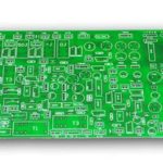
AR Device PCB Guide: Design, Manufacturing and Cost in 2025
Augmented reality is moving out of the laboratory and onto the faces, wrists, and workbenches of everyday users. AR glasses, AR head-mounted displays, and wearable display terminals are changing how people interact with digital information. Inside every one of these devices sits a small but decisive component: the AR device PCB. This printed circuit board is the central nervous system of AR hardware. It connects the processor, sensors, cameras, display drivers, and power modules into one working product. Understanding what an AR device PCB is, how it is designed, and what it costs is essential for any hardware team planning a 2025 AR launch. This guide explains the full picture in plain language.
What Is an AR Device PCB?
An AR device PCB is a high-performance circuit board designed specifically for augmented reality hardware. It integrates and controls the many miniature electronic components that make AR experiences possible. Unlike ordinary consumer electronics boards, AR device PCBs must deliver high-speed signal transmission, high-density assembly, and tight coordination between multiple sensors inside a very limited physical space.
Consider a typical AR glasses frame. Inside that slim structure, the PCB connects motion sensors, the display driver, power management circuitry, wireless modules, cameras, and microphones. Every trace must fit into a board area that is often smaller than a credit card. To achieve this, AR circuit boards rely on advanced techniques such as multilayer stacking, fine-line routing, embedded components, and rigid-flex construction.
The result is a board that is simultaneously light, thin, flexible where it needs to bend around the frame, and durable enough for daily wear. The difference between a polished AR product and a clunky prototype is usually hidden inside this board. That is why serious manufacturers treat the AR device PCB as a core engineering asset rather than an off-the-shelf part.
How an AR Device PCB Works
An AR device PCB acts as the communication center of the whole hardware system. It processes input in real time and routes signals to the right destination. Cameras capture the physical world, sensors track head and hand movement, and microphones collect voice commands. The board passes this data to the processor, which computes the augmented overlay. Finally, the display driver receives the rendered image and projects it in front of the user’s eyes.
Signal processing demands speed. In a high-end AR headset, sensor fusion and display synchronization must complete within milliseconds, otherwise the user experiences latency, drift, or motion sickness. The PCB supports this timing budget with careful impedance control, controlled trace lengths, and dedicated ground planes that preserve signal integrity at high frequencies.
Power distribution is just as important. Battery-powered AR wearables need stable current for low-power modules that must run all day. The board includes dedicated power planes, decoupling capacitors, and battery management circuits that prevent voltage drop during sudden processor bursts. Wireless communication over Bluetooth and Wi-Fi also depends on a clean antenna design and properly isolated RF sections on the board. Every function traces back to the layout quality of the AR device PCB.
Key Components on an AR Board
A typical AR device PCB design carries several functional groups. The microprocessor or system-on-chip executes the AR computation workload, including computer vision and rendering. Memory modules store 3D map data, sensor calibration files, and application code. The inertial measurement unit, or IMU, detects spatial orientation and motion. Camera modules capture video frames for tracking. Display drivers control the micro-OLED or waveguide-based optical engine. Wireless modules provide Bluetooth and Wi-Fi connectivity. Power management ICs regulate the battery supply.
Material selection is equally specific. Standard FR-4 handles simple rigid sections, while polyimide is used where the board must flex around the frame. Many AR products combine both in a rigid-flex structure: rigid islands carry the active components, and flexible bridges connect them around corners and hinges. This hybrid approach removes fragile connectors and reduces total thickness. Designers also choose low-loss laminates near high-speed data lines and carefully position the antenna keep-out zones. Each choice affects performance, reliability, and ultimately cost.

Design Challenges in AR PCB Engineering
AR device PCB design is among the most demanding work in electronics today because performance, thermal control, and size must be balanced simultaneously.
Miniaturization. Every millimeter of board space is expensive inside a wearable. Engineers use high-density interconnect layouts, microvias, and fine-pitch ball grid array packages to shrink the footprint. Multilayer stacking packs more routing into less area, but each added layer increases fabrication cost and complexity.
Thermal management. High-performance chips generate heat inside a sealed frame with almost no airflow. Thermal copper planes, heat-spreading layers, and thermal vias pull heat away from the processor toward the outer frame. Without this design work, the device throttles performance or shortens battery life.
EMI and EMC control. Cameras, radios, and displays operate in close proximity, so interference is a constant risk. Careful grounding, shielding, and separation of sensitive analog and RF traces keep signals clean. Certification testing is much smoother when EMI is addressed during layout rather than patched later.
Flex durability. Wearable products are folded, bent, and dropped. Flexible sections need controlled bend radii, tear-resistant copper, and strain relief at transition points. A rigid-flex board engineered for millions of flex cycles protects the product investment over its lifetime.
Experienced engineering teams address these issues before fabrication through a thorough design-for-manufacturability review. Catching a clearance or stack-up problem in the file stage saves weeks of rework later. A manufacturer with in-house design support, like the team behind PCB manufacturing at gopcb, can validate the layout before any material is cut.
AR Device PCB Manufacturing Process
Producing an AR device circuit board requires precision process control at every step. The flow begins with stack-up design and layer layout, followed by lamination of the rigid and flexible sections. Laser drilling creates the microvias that connect high-density layers, and copper plating forms the conductive walls. Etching defines the fine-line circuitry, after which the board receives a surface finish such as ENIG, OSP, or immersion silver, chosen for the assembly method and reliability needs.
Surface-mount assembly follows. Tiny components are placed by automated SMT lines and reflow soldered with carefully profiled temperatures. Because AR boards mix fine-pitch ICs, BGAs, and thin flexible areas, solder paste volume and placement accuracy must be tightly controlled.
Testing closes the loop. Automated optical inspection checks component placement and solder joints, while electrical testing verifies continuity and isolation on every net. Rigid-flex assemblies may receive additional bend-cycle and thermal-cycling samples. All of this is supported by PCBA testing procedures aligned with IPC-6012, IPC-A-600, and RoHS requirements, giving hardware teams confidence before mass production.

AR Device PCB Price and Cost Factors in 2025
As of 2025, the average price of an AR device PCB generally ranges from about $40 to $120 per board, depending heavily on design and material specifications. That wide band reflects how different one AR product is from another.
The main cost drivers are board type, layer count, material, and order quantity. A rigid four-layer board with standard FR-4 is at the low end. A rigid-flex design with eight to twelve layers, polyimide flex sections, and controlled-impedance routing sits at the top of the range. High-frequency laminates near wireless modules add further cost, as do fine-line processes and microvia drilling.
Typical reference points in 2025 are useful for budgeting. Prototype quantities in the development phase commonly land between $45 and $70 per board. Volume production above 1,000 pieces brings pricing down to roughly $35 to $55 per board as setup and tooling costs spread across the order. Quick-turn prototype service is available from responsive suppliers when the schedule demands it, usually at a small premium.
Getting an accurate quotation requires complete information: Gerber files, stack-up requirements, material preferences, flex bend specifications, and expected volume. Transparent suppliers quote each cost element separately so there are no surprises when the first invoice arrives.
Global Supplier and Price Comparison
AR device PCB manufacturing prices and lead times differ significantly around the world. Chinese manufacturers typically quote $40 to $70 per board with seven to ten day prototype delivery. US suppliers range from $80 to $150 per board with twelve to twenty day lead times. European suppliers are similar at $90 to $160 per board with fifteen to twenty-five day schedules. The gap reflects labor rates, supply chain maturity, and process efficiency rather than quality differences.
This is why a growing number of AR hardware developers source from China. ISO- and RoHS-certified factories with automated SMT lines, 24-hour prototyping, and global logistics offer a competitive path to market. Working with one partner that controls fabrication and PCB assembly shortens communication loops and keeps quality accountability clear. For wearable products with tight time-to-market windows, a responsive Asian manufacturing partner is often the difference between hitting and missing the launch season.
Common AR PCB Problems and How to Prevent Them
AR device PCB projects tend to repeat the same failure patterns, and each has a known prevention.
Signal interference. Symptoms include dropped wireless connections or image artifacts. Prevention comes from proper grounding, layer stack-up, and RF isolation during layout.
Excessive heat. Processors throttle or the frame becomes uncomfortable. Thermal copper planes and heat-dissipating vias keep temperatures in check.
Flex fatigue. Cracks appear after repeated bending. Hybrid rigid-flex construction with controlled bend radii and tear-resistant materials extends life dramatically.
Solder joint fatigue. Small components lift off after thermal cycling. Gold-plated pads and reinforced pad designs improve long-term reliability in daily-wear products.
Choosing a manufacturer with substantial experience in wearable electronics lets you catch these risks during the prototype phase instead of in the field. A good partner reviews the layout, proposes design improvements, and validates the board under realistic conditions before volume starts. Reviewing the board against the documented PCB capabilities and the factory’s quality management system is the fastest way to confirm a supplier can actually deliver what the design demands.
Future Trends in AR Device PCB Technology
AR device PCB technology is evolving quickly alongside the products it powers. AI-assisted layout tools are already reducing design time by automatically optimizing component placement and routing. Ultra-thin flexible materials such as LCP and advanced polyimide formulations are shrinking board thickness while improving signal performance. Three-dimensional packaging and embedded components are moving passive parts inside the substrate, freeing surface area for active silicon. Environmentally friendly lead-free processes continue to replace older chemistries as global regulations tighten.
As AR devices become lighter, more intelligent, and more power-efficient, the PCB remains the platform on which all of that progress is built. Suppliers that invest in fine-line capability, rigid-flex experience, and automated inspection will be best positioned to serve the next generation of AR products. For hardware teams, locking in a manufacturing partner early, while the design is still flexible, is one of the most effective ways to keep both quality and budget under control.
Conclusion
The AR device PCB is not just a circuit board; it is the foundation of every augmented reality experience. Signal stability, thermal performance, and flex durability all depend on its design and fabrication quality. Whether you are developing AR glasses, a head-mounted display, or an industrial AR terminal, working with a qualified manufacturer from the prototype stage onward protects your schedule and your product’s reputation. With the right materials, rigorous testing, and responsive support, your AR hardware can reach the market faster, run more reliably, and scale more affordably.
Frequently Asked Questions
Q1. Which materials are suitable for AR device PCBs? Flexible polyimide and FR-4 composite laminates are the most common, offering a balance of thinness and bend resistance for wearable structures.
Q2. What is the 2025 prototype price for AR device PCBs? Prototypes typically cost $45 to $70 per board, depending on layer count, materials, and design complexity.
Q3. Can flexible PCBs be used in AR headsets? Yes, flexible PCB technology is ideal for wearable and curved AR structures, and rigid-flex combinations are frequently used in production designs.
Q4. Which testing standards apply to AR device PCBs? Common references include IPC-6012, IPC-A-600, and RoHS environmental compliance, plus electrical testing and AOI for every production batch.
Q5. How long does AR PCB production take? Prototypes usually take seven to ten working days, while volume production is typically completed within two to three weeks.